


In the realm of government and defense logistics, clarity in workflow definition is not just a convenience—it is a necessity. Defense Logistics Workflow Systems manage the critical end-to-end supply chain for military supplies, procurement, inventory, and distribution. These systems must be robust, auditable, and clearly understood by diverse stakeholders ranging from Logistics Officers to Compliance Auditors.
Visual modeling serves as the bridge between complex requirements and technical implementation. However, traditional drag-and-drop tools often struggle with versioning, consistency, and rapid iteration. Diagram-as-code methodologies, specifically using PlantUML, offer a superior alternative for architects. By treating diagrams as text, you gain reproducibility, diff-ability, and seamless integration into documentation pipelines.
This masterclass utilizes VPasCode, the free web-based diagram-as-code editor, to build a professional Use Case diagram. VPasCode enables instant browser-based rendering without local dependencies, allowing you to prototype complex government workflows in seconds. We will construct a system boundary, define primary and secondary actors, and map critical interactions for a Defense Logistics environment.
Understanding the Model: Purpose, Scope & Problem Framing
Diagram Abstraction & Representation
A Use Case diagram models the functional requirements of a system from the perspective of external actors. In this specific Defense Logistics context, the diagram serves to define who interacts with the system and what high-level goals they achieve.
- Actors: Represent human roles or external systems. We distinguish between Primary Actors (Logistics Officers, Warehouse Managers) who initiate the workflow, and Secondary Actors (Suppliers, Military Units) who support the process but do not control the core system functions.
- Use Cases: Represent specific goals or functions, such as “Manage Procurement Requests” or “Track Inventory Levels”.
- System Boundary: The rectangle enclosing the use cases defines the scope of the software system itself, separating internal functionality from external interaction.
Target Domain Scope & Scenario
This diagram focuses on the Defense Logistics Workflow System. It intentionally models the core administrative and logistical functions required to move supplies from procurement to the front lines. The scope includes procurement, inventory tracking, transportation scheduling, and compliance validation. It excludes lower-level database operations or specific hardware integrations, keeping the focus on business-level interactions.
Key Takeaways & Educational Insights
By completing this tutorial, you will gain:
- Boundary Clarity: Understanding how to encapsulate system functionality within a rectangle to define scope.
- Actor Differentiation: How to visually separate primary operators from secondary participants using layout positioning.
- Theme Customization: Leveraging
!themedirectives to match enterprise branding (e.g., AWS Orange for defense-tech aesthetics).
Complete Diagram & Full Source Code
Before diving into the step-by-step construction, review the finished blueprint. This diagram illustrates the complete interaction map for the Defense Logistics Workflow System.
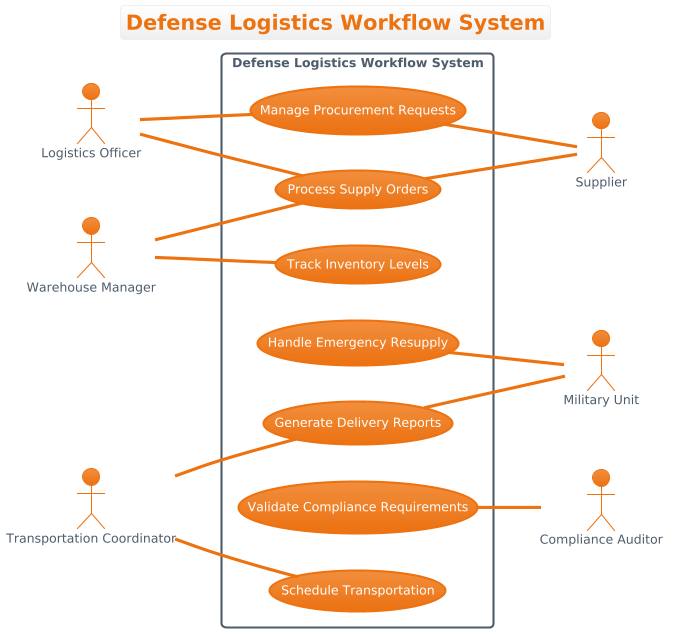
Copy the following code to use in the VPasCode editor. This single block contains the full configuration, actor definitions, system boundary, and relationships.
@startuml
!theme aws-orange

title Defense Logistics Workflow System

/'
This diagram illustrates the use cases for a Defense Logistics Workflow System.
The system manages the end-to-end logistics process for military supplies, including
procurement, inventory management, transportation, and distribution to various
military units and bases. Primary actors include Logistics Officers, Warehouse Managers,
and Transportation Coordinators who interact directly with the system. Secondary actors
include Suppliers, Military Units (recipients), and Compliance Auditors who are involved
in specific processes but do not directly operate the core system functions.
'/

left to right direction

actor "Logistics Officer" as LO
actor "Warehouse Manager" as WM
actor "Transportation Coordinator" as TC

rectangle "Defense Logistics Workflow System" {
    usecase "Manage Procurement Requests" as UC1
    usecase "Track Inventory Levels" as UC2
    usecase "Process Supply Orders" as UC3
    usecase "Schedule Transportation" as UC4
    usecase "Generate Delivery Reports" as UC5
    usecase "Validate Compliance Requirements" as UC6
    usecase "Handle Emergency Resupply" as UC7
}

actor "Supplier" as SUP
actor "Military Unit" as MU
actor "Compliance Auditor" as CA

' Primary actor associations
LO -- UC1
LO -- UC3
WM -- UC2
WM -- UC3
TC -- UC4
TC -- UC5


' Secondary actor associations
UC1 -- SUP
UC3 -- SUP
UC5 -- MU
UC6 -- CA
UC7 -- MU

@endumlStep-by-Step Architectural Walkthrough
Phase 1: Canvas Configuration & Layout Directives
Every robust diagram starts with a solid foundation. In PlantUML, this begins with the @startuml directive and theme selection. We begin by setting the visual identity of the diagram.
First, we apply the !theme aws-orange directive. This applies a professional, high-contrast color scheme suitable for enterprise or defense contexts, ensuring the diagram looks polished immediately.
!theme aws-orangeNext, we define the diagram’s flow direction. Standard UML often defaults to top-to-bottom, but for Use Case diagrams with many actors, a left-to-right layout is often clearer. This allows us to place primary actors on the left and secondary actors on the right, creating a natural reading flow.
left to right directionPhase 2: Declaring Core Entities, Actors, and Boundaries
With the canvas set, we define the participants. In VPasCode, you can define actors anywhere in the code; the layout engine will position them based on the relationships.
We declare the Primary Actors first. These are the users directly operating the system.
actor "Logistics Officer" as LO
actor "Warehouse Manager" as WM
actor "Transportation Coordinator" as TC
Next, we define the System Boundary. The rectangle keyword encapsulates all internal use cases, clearly demarcating the system’s scope from external entities.
rectangle "Defense Logistics Workflow System" {
    usecase "Manage Procurement Requests" as UC1
    usecase "Track Inventory Levels" as UC2
    usecase "Process Supply Orders" as UC3
    usecase "Schedule Transportation" as UC4
    usecase "Generate Delivery Reports" as UC5
    usecase "Validate Compliance Requirements" as UC6
    usecase "Handle Emergency Resupply" as UC7
}
Finally, we declare the Secondary Actors who interact with specific functions but are not system operators.
actor "Supplier" as SUP
actor "Military Unit" as MU
actor "Compliance Auditor" as CA
Phase 3: Mapping Data Flows & Key Interactions
The core value of a Use Case diagram lies in the associations. We use the -- syntax to create associations without arrowheads, indicating a bidirectional or general relationship, which is standard for actor-use case connections.
We connect Primary Actors to their respective functions. For instance, the Logistics Officer initiates procurement and supply orders.
LO -- UC1
LO -- UC3
Similarly, we map Secondary Actors to the specific use cases they influence. For example, Suppliers provide inputs to Procurement and Supply Orders, while Military Units receive deliveries.
UC1 -- SUP
UC3 -- SUP
UC5 -- MU
UC7 -- MU
Phase 4: Grouping, Annotations & Visual Polish
To ensure the diagram is self-documenting, we add a title and a comment block. The title directive appears at the top of the rendered diagram.
title Defense Logistics Workflow SystemWe also include a description block using the /' and '/ syntax. This text does not render as a graphic element but provides context for anyone reading the source code or the diagram metadata.
/'
This diagram illustrates the use cases for a Defense Logistics Workflow System...
'/
Syntax & Keyword Deep Dive
Understanding the specific PlantUML syntax used in this diagram empowers you to modify it for future projects.
!theme: Sets the global color palette and styling.aws-orangeprovides a distinct, professional look.left to right direction: Overrides the default vertical layout, forcing a horizontal flow which is ideal for actor-centric diagrams.actor: Defines a participant. Theaskeyword assigns an alias (e.g.,as LO) to simplify relationship definitions.rectangle: Creates the system boundary box. Everything inside is considered part of the system.usecase: Defines a functional requirement. Using aliases (e.g.,as UC1) helps keep relationship lines clean and readable.--: Creates an association link. Unlike-->, this does not add an arrowhead, which is the standard convention for Actor-to-UseCase relationships./' ... '/: Creates a comment block. This is excellent for including requirements context or design notes directly within the code.
Best Practices & Pitfalls to Avoid
When building diagrams for government or enterprise systems, adherence to modeling standards ensures clarity and maintainability.
- Maintain Clear Boundaries: Always enclose use cases in a rectangle. This prevents confusion about which functionality belongs to the system versus external dependencies.
- Consistent Naming: Use action-oriented names for use cases (e.g., “Manage Procurement” rather than “Procurement”) to clearly indicate the goal of the interaction.
- Limit Scope: Do not attempt to model every single click or database transaction in a Use Case diagram. Focus on high-level goals and user roles.
- Use Aliases: Always assign aliases to actors and use cases. This keeps the relationship lines clean and allows you to reference complex names easily.
Try It Yourself with VPasCode
Start Building Defense Logistics Diagrams Faster with VPasCode
Instantly render and customize your Use Case diagrams online in VPasCode without installing any tools or configuring local environments.