


In the rapidly evolving landscape of FinTech, clarity is currency. When designing a Robo-Advisor Platform, architects face the complex challenge of defining system boundaries, user roles, and functional requirements without getting bogged down in implementation details. Visual modeling is not merely about drawing pictures; it is about establishing a shared language between stakeholders, developers, and business analysts.

A Use Case Diagram is the ideal tool for this architectural phase. It provides a high-level view of the system’s functionality from the perspective of external actors. By utilizing diagram-as-code with PlantUML in VPasCode, financial architects can rapidly prototype these models, ensure consistency across documentation, and visualize the interaction between investors, administrators, and external financial gateways instantly in the browser.
This tutorial serves as a masterclass in modeling a Robo-Advisor ecosystem. We will move beyond basic syntax to explore how to structure a professional diagram that accurately reflects the flow of funds, risk assessment, and portfolio management within a secure financial environment.
Understanding the Model: Purpose, Scope & Problem Framing
Diagram Abstraction & Representation
A Use Case Diagram abstracts the system into two primary components: Actors and Use Cases. In the context of a Robo-Advisor Platform, actors represent the distinct user roles or external systems that interact with the software. They do not represent internal classes or database tables, but rather the entities initiating actions.
Use Cases, conversely, represent the functional goals or services the system provides to these actors. They answer the question: “What can the system do for the user?” For example, “Deposit Funds” is a use case, while “Database Transaction Handler” is an internal implementation detail that should not appear in this diagram.
Target Domain Scope & Scenario
This model focuses specifically on the core interaction layer of a Robo-Advisor Platform. The scope includes:
- Investor Interactions: Onboarding, risk profiling, and portfolio management.
- Administrative Control: User management and strategy configuration.
- External Integrations: Payment processing and real-time market data feeds.
By isolating these elements, we define the system boundary clearly. Anything outside the rectangle (like the Payment Gateway) is an external dependency, while anything inside is core functionality.
Key Takeaways & Educational Insights
Through building this diagram, you will gain architectural insights into:
- How to separate internal system logic from external dependencies.
- The importance of defining clear actor responsibilities (e.g., Admin vs. Investor).
- How to use PlantUML to maintain documentation that evolves with your codebase.
Complete Diagram & Full Source Code
Before diving into the construction phases, visualize the finished blueprint. Below is the complete source code for the Robo-Advisor Use Case Diagram. This code utilizes the VPasCode theme for consistent styling.
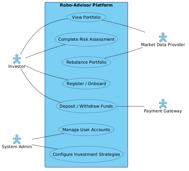
@startuml
left to right direction
skinparam actorStyle hollow
!include https://static.visual-paradigm.com/web/resources/plantuml-stdlib/themes/vp.puml

skinparam defaultTextAlignment center

actor "Investor" as investor
actor "System Admin" as admin

rectangle "Robo-Advisor Platform" {
    usecase "Register / Onboard" as UC1
    usecase "Complete Risk Assessment" as UC2
    usecase "View Portfolio" as UC3
    usecase "Deposit / Withdraw Funds" as UC4
    usecase "Rebalance Portfolio" as UC5
    usecase "Manage User Accounts" as UC6
    usecase "Configure Investment Strategies" as UC7
}

actor "Payment Gateway" as payment
actor "Market Data Provider" as market

investor -- UC1
investor -- UC2
investor -- UC3
investor -- UC4

admin -- UC6
admin -- UC7

UC4 -- payment
UC3 -- market
UC5 -- market

@endumlStep-by-Step Architectural Walkthrough
Building a professional diagram requires a structured approach. We will construct this model in four distinct phases, ensuring that every line of code serves a specific architectural purpose.
Phase 1: Canvas Configuration & Layout Directives
Every PlantUML diagram starts with configuration directives that set the stage for the rendering engine. We begin by defining the layout direction and the visual theme.
First, we set the reading direction to flow naturally from left to right, which is standard for most Western business diagrams:
left to right directionNext, we apply the VPasCode theme. This ensures the diagram looks consistent with other Visual Paradigm assets and provides a modern, clean aesthetic. We also define the actor style to be “hollow,” which is a common convention for external actors in financial diagrams:
skinparam actorStyle hollow
!include https://static.visual-paradigm.com/web/resources/plantuml-stdlib/themes/vp.puml
Finally, we center the text alignment for better readability within the use case boxes:
skinparam defaultTextAlignment centerPhase 2: Declaring Core Entities, Actors, and Boundaries
Once the canvas is ready, we declare the participants. In a Use Case Diagram, actors are the initiators of actions. We define the primary users of the Robo-Advisor platform:
actor "Investor" as investor
actor "System Admin" as admin
Here, we assign aliases (e.g., as investor) to make the subsequent connection lines more readable. The next critical step is defining the system boundary. We use a rectangle to encapsulate the core functionality of the “Robo-Advisor Platform”:
rectangle "Robo-Advisor Platform" {
    // Use cases go here
}
Inside this boundary, we list the specific functional goals. These are the use cases that the system must support to be viable in the finance industry:
usecase "Register / Onboard" as UC1
usecase "Complete Risk Assessment" as UC2
usecase "View Portfolio" as UC3
usecase "Deposit / Withdraw Funds" as UC4
usecase "Rebalance Portfolio" as UC5
usecase "Manage User Accounts" as UC6
usecase "Configure Investment Strategies" as UC7
Phase 3: Mapping Data Flows & Key Interactions
With actors and use cases defined, we map the relationships. This is where the logic of the system comes alive. We use the double-dash -- to indicate an association between an actor and a use case.
For the Investor, the diagram shows they can perform onboarding, risk assessment, view their holdings, and manage funds:
investor -- UC1
investor -- UC2
investor -- UC3
investor -- UC4
For the System Admin, the focus is on backend management:
admin -- UC6
admin -- UC7
This separation of concerns is vital for security modeling in finance, ensuring that admin tasks do not overlap with investor-facing transactions unless necessary.
Phase 4: Grouping, Annotations & Visual Polish
A complete architecture model accounts for external dependencies. A Robo-Advisor cannot function without money moving or prices updating. We declare these external actors outside the system rectangle:
actor "Payment Gateway" as payment
actor "Market Data Provider" as market
We then connect specific use cases to these external systems. For instance, depositing funds requires a Payment Gateway, and viewing or rebalancing a portfolio requires real-time Market Data:
UC4 -- payment
UC3 -- market
UC5 -- market
This final phase clarifies the system’s dependencies, making it easier for backend engineers to identify API integrations required during development.
Syntax & Keyword Deep Dive
To master PlantUML, you must understand the specific keywords that control the diagram’s structure. Here is a breakdown of the syntax used in this Robo-Advisor model:
actor: Declares an external entity interacting with the system. In finance, this could be a user, a bank, or a regulatory body.usecase: Defines a specific function or goal the system performs. It is the core unit of requirement modeling.rectangle: Creates a boundary box to group use cases belonging to a specific system context. This visually separates the “System Under Design” from the environment.--: The association operator. It draws a line between two elements, indicating a relationship or interaction flow.!include: A directive to import external style definitions. This allows you to reuse themes and libraries without rewriting CSS-like parameters.skinparam: Controls the visual appearance, such as font size, color, and actor shape (e.g.,actorStyle hollow).
Best Practices & Pitfalls to Avoid
When modeling financial systems with VPasCode, adhere to these best practices to ensure your diagrams remain useful over time:
- Keep Boundaries Clear: Do not include internal database tables or API endpoints inside the
rectangle. Use cases should represent business value, not technical implementation. - Use Meaningful Aliases: Always assign aliases to actors (e.g.,
as investor) to keep your association lines readable and concise. - Group External Systems: If you have multiple external dependencies (like banks, tax services, and market data), consider grouping them visually or using distinct naming conventions to avoid clutter.
- Version Your Diagrams: While VPasCode is a browser tool, save your source code as a .plantuml file in your documentation repository to track changes manually.
Start Building Use Case Diagrams Faster with VPasCode
Instantly prototype your Robo-Advisor architecture and test syntax changes in your browser without installing any tools.