


In the fast-paced environment of modern manufacturing, the efficiency of an Enterprise Resource Planning (ERP) system often hinges on the clarity of its underlying business processes. One of the most critical workflows is raw material procurement. A breakdown in this process can lead to production delays, inventory shortages, or budget overruns. While text-based specifications exist, they often fail to capture the nuances of decision logic, parallel tasks, and handoffs between different organizational units.

This is where diagramming-as-code with PlantUML shines. By defining workflows in text, architects can version their documentation alongside code, ensuring that visual models evolve with the system. Using VPasCode, a free web-based diagram editor, teams can prototype these complex flows instantly without installing Java or configuring local build environments. This tutorial demonstrates how to construct a professional activity diagram for a raw material procurement process, leveraging swimlanes to clarify responsibilities and conditional logic to handle negotiation scenarios.
Understanding the Model: Purpose, Scope & Problem Framing
Before diving into the syntax, it is essential to understand what this specific model represents and why an activity diagram is the appropriate abstraction for this problem.
Diagram Abstraction & Representation
An activity diagram in PlantUML is designed to model the flow of control from activity to activity. Unlike sequence diagrams that focus on object interactions over time, activity diagrams focus on the what and how of a process. In this manufacturing context, the diagram models:
- State Transitions: Moving from a requisition to a purchase order (PO).
- Decision Logic: Handling scenarios where quotations are rejected or negotiations fail.
- Concurrency: Managing parallel activities like inventory storage and defect returns.
Target Domain Scope & Scenario
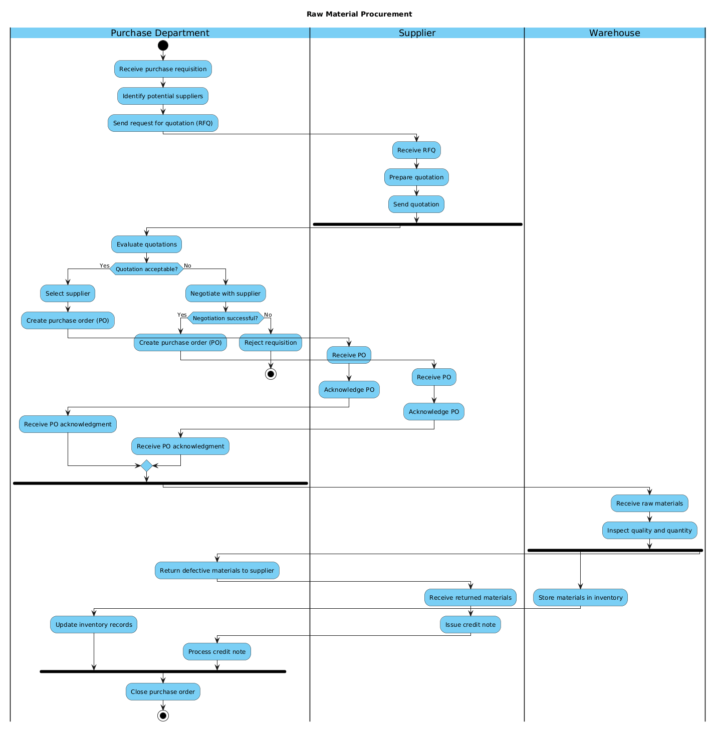
The scope of this diagram is strictly the procurement lifecycle. It begins when the Purchase Department receives a requisition and ends when the purchase order is closed. It explicitly excludes downstream manufacturing execution or upstream supplier production, focusing instead on the transactional bridge between the buyer and the vendor.
Key Takeaways & Educational Insights
By building this model in VPasCode, you will gain insight into:
- Boundary Clarity: How swimlanes visually separate the responsibilities of the Purchase Department, Suppliers, and Warehouse.
- Exception Handling: How to model “No” paths for negotiation failures without cluttering the main flow.
- Parallelism: How to represent simultaneous tasks, such as storing good materials while returning defective ones.
Complete Diagram & Full Source Code
Below is the final blueprint for the Raw Material Procurement process. You can view the rendered result immediately by pasting the code below into the VPasCode editor.
@startuml
!include https://static.visual-paradigm.com/web/resources/plantuml-stdlib/themes/vp.puml

title Raw Material Procurement

|Purchase Department|
start
:Receive purchase requisition;
:Identify potential suppliers;
:Send request for quotation (RFQ);

|Supplier|
:Receive RFQ;
:Prepare quotation;
:Send quotation;

fork
|Purchase Department|
:Evaluate quotations;
if (Quotation acceptable?) then (Yes)
  :Select supplier;
  :Create purchase order (PO);
  |Supplier|
  :Receive PO;
  :Acknowledge PO;
  |Purchase Department|
  :Receive PO acknowledgment;
else (No)
  :Negotiate with supplier;
  if (Negotiation successful?) then (Yes)
    :Create purchase order (PO);
    |Supplier|
    :Receive PO;
    :Acknowledge PO;
    |Purchase Department|
    :Receive PO acknowledgment;
  else (No)
    :Reject requisition;
    stop
  endif
endif
endfork

|Warehouse|
:Receive raw materials;
:Inspect quality and quantity;

fork
  :Store materials in inventory;
  |Purchase Department|
  :Update inventory records;
fork again
  :Return defective materials to supplier;
  |Supplier|
  :Receive returned materials;
  :Issue credit note;
  |Purchase Department|
  :Process credit note;
end fork

|Purchase Department|
:Close purchase order;
stop

@endumlStep-by-Step Architectural Walkthrough
Building this diagram in VPasCode is a modular process. We will break the construction down into four logical phases: configuration, lane declaration, flow logic, and parallel handling.
Phase 1: Canvas Configuration & Layout Directives
The first step is setting the stage. We need to load the VPasCode theme to ensure the diagram looks professional and consistent with the editor’s branding. We also define the title for the diagram.
Start with the standard PlantUML header and the theme include:
@startuml
!include https://static.visual-paradigm.com/web/resources/plantuml-stdlib/themes/vp.puml

title Raw Material Procurement
This ensures that when you render the diagram in the browser, it uses the correct skin parameters for fonts, colors, and borders.
Phase 2: Declaring Core Entities, Actors, and Boundaries
In an activity diagram, swimlanes are crucial for showing who is responsible for what. We define these using the pipe syntax |Label|.
We start with the initiator of the process, the Purchase Department:
|Purchase Department|
start
:Receive purchase requisition;
:Identify potential suppliers;
:Send request for quotation (RFQ);
Next, we switch lanes to the external actor, the Supplier:
|Supplier|
:Receive RFQ;
:Prepare quotation;
:Send quotation;
Switching lanes visually indicates a handoff of responsibility. The flow moves from the internal department to the external vendor and back.
Phase 3: Mapping Data Flows & Key Interactions
This phase handles the core logic. We use a fork block to introduce a decision point regarding the quotation evaluation. This allows us to split the flow into a “Yes” path and a “No” path.
The conditional logic is structured as follows:
fork
|Purchase Department|
:Evaluate quotations;
if (Quotation acceptable?) then (Yes)
  :Select supplier;
  :Create purchase order (PO);
  ...
else (No)
  :Negotiate with supplier;
  ...
endif
endfork
Notice the nested if statement within the “No” path. This models the negotiation loop. If negotiation fails, the process terminates with a stop node, clearly indicating a dead end in the workflow.
Phase 4: Grouping, Annotations & Visual Polish
The final phase involves handling parallel activities after the materials arrive at the warehouse. In manufacturing, inspection often happens simultaneously with storage updates or defect returns. We use the fork and fork again syntax to achieve this concurrency.
|Warehouse|
:Receive raw materials;
:Inspect quality and quantity;

fork
  :Store materials in inventory;
  |Purchase Department|
  :Update inventory records;
fork again
  :Return defective materials to supplier;
  ...
end fork

|Purchase Department|
:Close purchase order;
stop
The fork again directive allows us to start a second concurrent branch without closing the first fork block immediately. This visualizes that storage updates and defect returns can happen in parallel before the process closes.
Syntax & Keyword Deep Dive
To master this diagram type, you must understand the specific PlantUML keywords used to control flow and structure.
start/stop: Defines the entry and exit points of the activity. Every valid activity diagram must have exactly one start and one stop node.|Lane Name|: Creates a swimlane. This is the primary mechanism for assigning responsibility in this diagram.fork/end fork: Creates a branch in the flow. It allows the diagram to split into multiple paths based on conditions.if (Condition) then (Yes): The standard syntax for decision nodes. The text inside parentheses represents the label for the outgoing arrow.fork again: Specifically used to add a parallel branch to an existing fork block, enabling complex concurrency like the inventory/defect split.:Action;: The colon denotes an activity (action) node. The text following the colon is the label for the action.
Best Practices & Pitfalls to Avoid
When modeling manufacturing workflows in VPasCode, adhere to these guidelines to maintain clarity:
- Limit Swimlane Complexity: Do not create too many swimlanes. If you have more than 5-6, consider splitting the diagram into sub-processes to avoid horizontal scrolling issues.
- Keep Decisions Binary: While PlantUML supports multiple branches, try to keep decision nodes binary (Yes/No) for readability. Complex multi-way decisions often confuse stakeholders.
- Use Meaningful Labels: Avoid generic labels like “Process Data.” Use specific actions like “Receive PO Acknowledgment” to ensure the diagram remains self-documenting.
- Validate Parallelism: Ensure that
forkandfork againblocks are properly closed withend fork. Mismatched blocks will cause rendering errors in the browser.
Try It Yourself with VPasCode
Start Building PlantUML Activity Diagrams Faster with VPasCode
Test, preview, and customize this manufacturing workflow diagram online in VPasCode without installing any tools.