


In the complex landscape of modern manufacturing, Industrial Automation Systems (IAS) serve as the central nervous system for production lines. These systems integrate machinery, environmental controls, and data logging to ensure efficiency and safety. However, as these systems grow in complexity, communicating their functional requirements to stakeholders becomes challenging. Misalignment between human operators, engineers, and external systems like MES or SCADA can lead to operational gaps.

Visual modeling provides the necessary clarity to bridge this gap. By using a diagram-as-code approach with PlantUML, architects can define system boundaries, actor interactions, and functional goals in a text-based format that is version-safe and easily maintainable. VPasCode enhances this workflow by offering an instant, browser-based rendering engine. This allows engineers to prototype use case diagrams without installing local dependencies, ensuring that documentation evolves alongside the system architecture.
Understanding the Model: Purpose, Scope & Problem Framing
Before diving into the syntax, it is essential to understand the abstraction being modeled. A Use Case Diagram captures the functional requirements of a system from the perspective of external actors. It answers the question: “What does the system do, and who interacts with it?”
Diagram Abstraction & Representation
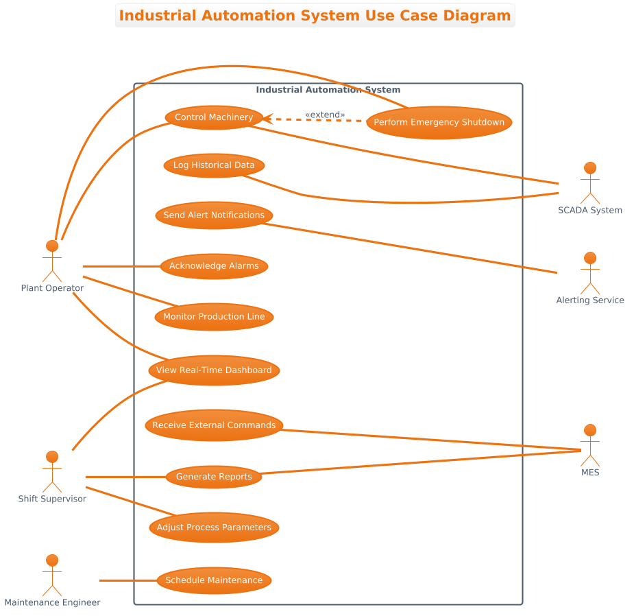
In this scenario, the diagram models an Industrial Automation System. The core abstraction involves defining the system boundary (the rectangle) and separating internal functionality (use cases) from external entities (actors). Primary actors represent human roles such as Operators and Supervisors who initiate actions. Secondary actors represent external systems or services like SCADA or Alerting Services that provide data or receive notifications.
Target Domain Scope & Scenario
The scope of this model covers the interaction between human personnel and the automation infrastructure. It intentionally excludes internal software logic (like class structures) or detailed data flows (like sequence diagrams), focusing instead on high-level functional access. This ensures that stakeholders can quickly validate if all necessary operational roles have defined access to critical functions like Emergency Shutdown or Maintenance Scheduling.
Key Takeaways & Educational Insights
- Boundary Clarity: Learn how to visually group related use cases within a system rectangle to define the scope of the IAS.
- Actor Differentiation: Understand the distinction between human actors (left) and system actors (right) to clarify responsibility.
- Relationship Semantics: Master the difference between standard associations and optional behaviors like
<<extend>>.
Complete Diagram & Full Source Code
Below is the finalized blueprint for the Industrial Automation System Use Case Diagram. You can view the rendered output immediately below, followed by the complete source code required to generate it.
@startuml
!theme aws-orange
title Industrial Automation System Use Case Diagram

/'
This use case diagram models the key functionalities of an Industrial Automation System (IAS)
used in a manufacturing plant. The system monitors and controls production lines, machinery,
and environmental conditions. Primary actors represent human operators and engineers who
actively interact with the system, while secondary actors represent external systems that
provide or receive data to support automation, logging, and alerting. The diagram includes
an extend relationship to show optional or conditional behavior.
'/

left to right direction

rectangle "Industrial Automation System" {
  usecase "Monitor Production Line" as UC1
  usecase "Control Machinery" as UC2
  usecase "Adjust Process Parameters" as UC3
  usecase "View Real-Time Dashboard" as UC4
  usecase "Acknowledge Alarms" as UC5
  usecase "Generate Reports" as UC6
  usecase "Schedule Maintenance" as UC7
  usecase "Log Historical Data" as UC8
  usecase "Send Alert Notifications" as UC9
  usecase "Receive External Commands" as UC10
  usecase "Perform Emergency Shutdown" as UC11

  ' Extend relationship: emergency shutdown extends control machinery (optional/conditional)
  UC2 <.. UC11 : <<extend>>
}

' Primary Actors (left side)
actor "Plant Operator" as Operator
actor "Shift Supervisor" as Supervisor
actor "Maintenance Engineer" as Engineer

Operator -- UC1
Operator -- UC2
Operator -- UC4
Operator -- UC5
Operator -- UC11

Supervisor -- UC3
Supervisor -- UC4
Supervisor -- UC6

Engineer -- UC7

' Secondary Actors (right side)
actor "SCADA System" as SCADA
actor "MES" as MES
actor "Alerting Service" as AlertService

UC2 --- SCADA
UC8 --- SCADA
UC10 --- MES
UC9 --- AlertService
UC6 --- MES

@endumlStep-by-Step Architectural Walkthrough
Constructing this diagram requires a logical flow from configuration to entity declaration, and finally to relationship mapping. We will break this down into four distinct phases.
Phase 1: Canvas Configuration & Layout Directives
Every PlantUML diagram begins with initialization directives that set the visual theme and orientation. In this manufacturing context, we use the aws-orange theme to provide a professional, warm industrial look. We also define a descriptive title and a comment block to explain the diagram’s context to future readers.
@startuml
!theme aws-orange
title Industrial Automation System Use Case Diagram

/'
This use case diagram models the key functionalities...
'/

left to right direction
The left to right direction directive ensures that actors flow naturally from left to right, which aligns with standard reading patterns and separates primary human actors from secondary system actors.
Phase 2: Declaring Core Entities, Actors, and Boundaries
Next, we define the system boundary using the rectangle keyword. Inside this boundary, we declare the usecase elements. Each use case is assigned a unique alias (e.g., UC1) to simplify relationship definitions later. Simultaneously, we declare the actor elements outside the rectangle to represent the external entities.
rectangle "Industrial Automation System" {
  usecase "Monitor Production Line" as UC1
  usecase "Control Machinery" as UC2
  usecase "Perform Emergency Shutdown" as UC11
}

actor "Plant Operator" as Operator
actor "SCADA System" as SCADA
Note that actors are declared globally, while use cases are scoped within the system rectangle. This clearly delineates what is internal to the automation logic versus who interacts with it.
Phase 3: Mapping Data Flows & Key Interactions
With entities defined, we establish the connections. Standard associations use a double hyphen -- to indicate a direct interaction. For example, the Operator interacts with UC1. We also define relationships with secondary actors, such as the SCADA system receiving data from UC2 (Control Machinery) using a triple hyphen --- to denote a stronger or system-level connection.
Operator -- UC1
UC2 --- SCADA
UC6 --- MES
Crucially, we model optional behavior using the extend relationship. The Emergency Shutdown is not always active but extends Control Machinery under specific conditions.
UC2 <.. UC11 : <<extend>>Phase 4: Grouping, Annotations & Visual Polish
Finally, we ensure the diagram is readable by using aliases (e.g., as UC1) to keep the code clean. We also include a comment block using /' and '/ to provide architectural context without cluttering the rendering engine. This documentation practice is vital for maintaining living diagrams over time.
Syntax & Keyword Deep Dive
Understanding the specific PlantUML syntax is key to mastering diagram-as-code. Here are the critical keywords used in this model:
!theme: Sets the global visual style for the diagram, such asaws-orangefor a consistent look.rectangle: Defines the system boundary, grouping related use cases together to show scope.actor: Declares an external entity (human or system) that interacts with the use cases.usecase: Defines a specific function or goal the system provides, assigned an alias for linking.--: Creates a standard association line between an actor and a use case without arrowheads.<..: Creates a dotted line used specifically for<<extend>>relationships to denote optional behavior./' ... '/: Wraps a multi-line comment that appears in the documentation but does not render as a diagram element.
Best Practices & Pitfalls to Avoid
To maintain high-quality architectural documentation, adhere to these modeling guidelines:
- Separate Human and System Actors: Visually group human operators on the left and external systems on the right. This reduces cognitive load when reviewing the diagram.
- Use Meaningful Aliases: Always assign aliases (e.g.,
as UC1) to use cases. This prevents long text strings from cluttering the relationship lines. - Limit Use Case Granularity: Ensure each use case represents a single, cohesive goal. Avoid combining “Monitor” and “Control” into one use case unless they are inseparable.
- Document Context: Use the comment block syntax to explain the diagram’s purpose. This helps future maintainers understand the “why” behind the model.
Try It Yourself with VPasCode
Start Building PlantUML Use Case Diagrams Faster with VPasCode
Instantly prototype and customize your Industrial Automation System diagrams online in VPasCode without installing any tools.