


Introduction to Logistics Process Modeling
In the high-stakes world of global freight and logistics, clarity is currency. A single misunderstanding in the customs clearance process can lead to costly delays, seized cargo, or compliance violations. For architects and logistics managers, visualizing these workflows is not just a documentation exercise; it is a critical risk management strategy. However, traditional drag-and-drop diagramming tools often struggle to maintain version consistency or scale well across large enterprise systems.

This is where diagram-as-code shines. By defining workflows in text using PlantUML, teams can version their diagrams alongside their source code, automate updates, and ensure that visual documentation remains synchronized with actual operational procedures. Using VPasCode, a free web-based diagram-as-code editor, you can prototype these complex logistics flows instantly without installing local dependencies or configuring build environments.
In this masterclass, we will construct a comprehensive activity diagram representing the Customs Clearance Process for a Global Freight System. We will leverage swimlanes to distinguish responsibilities between the Forwarding Agent and the Customs System, while implementing conditional branching and parallel processing to reflect real-world decision logic.
Understanding the Model: Purpose, Scope & Problem Framing
Before diving into the syntax, it is essential to understand the architectural abstraction we are modeling. An activity diagram in this context serves as a functional blueprint of the system’s operational state transitions. Unlike a sequence diagram that focuses on message timing, an activity diagram emphasizes the flow of control and decision points.
Diagram Abstraction & Representation
This model abstracts the physical movement of goods into a logical workflow. We represent the Forwarding Agent as the initiator of the process, responsible for documentation and coordination. The Customs System acts as the regulatory gatekeeper, performing risk assessments and issuing release orders. Swimlanes are crucial here; they visually separate the domains of responsibility, making it immediately clear which actor triggers which action.
Target Domain Scope & Scenario
The scope of this diagram covers the specific interval from the receipt of shipping documents to the final arrangement of cargo pickup. It intentionally excludes the physical transportation leg (truck or ship movement) to focus purely on the administrative and regulatory clearance workflow. Key dependencies include the accuracy of the HS code classification, the completeness of documentation, and the outcome of risk assessments.
Key Takeaways & Educational Insights
By building this model, you will gain insights into:
- Responsibility Boundaries: How swimlanes clarify ownership of specific tasks.
- Decision Logic: How to model binary decisions (e.g., Inspection Required) and their downstream impacts.
- Parallel Processing: How to represent simultaneous checks (e.g., Valuation and Restricted Goods) using fork nodes.
Complete Diagram & Full Source Code
Below is the complete blueprint for the Customs Clearance Process. This diagram utilizes the rose theme for a professional aesthetic and includes the necessary PlantUML directives to render swimlanes and conditional flows correctly.
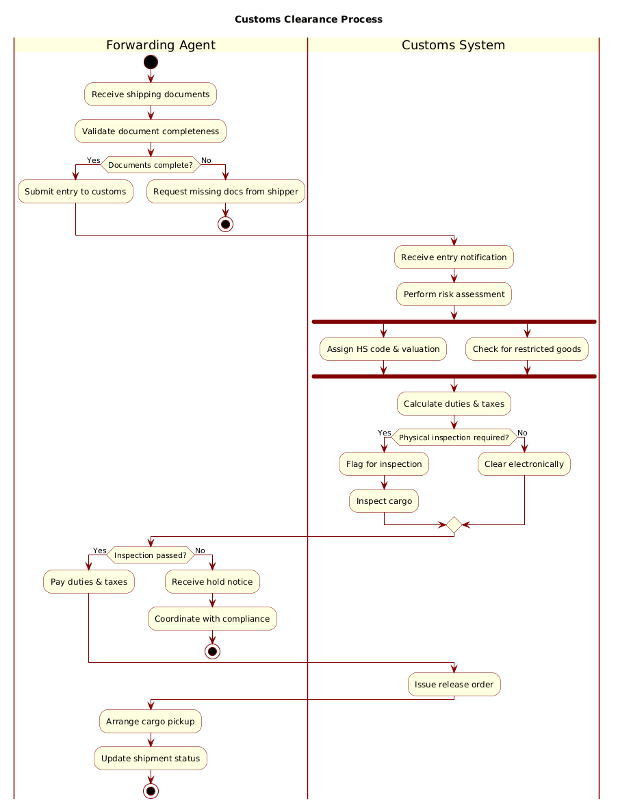
@startuml
!include https://static.visual-paradigm.com/web/resources/plantuml-stdlib/themes/rose.puml

title Customs Clearance Process

|Forwarding Agent|
start
:Receive shipping documents;
:Validate document completeness;

if (Documents complete?) then (Yes)
  :Submit entry to customs;
else (No)
  :Request missing docs from shipper;
  stop
endif

|Customs System|
:Receive entry notification;
:Perform risk assessment;

fork
  :Assign HS code & valuation;
fork again
  :Check for restricted goods;
end fork

:Calculate duties & taxes;

if (Physical inspection required?) then (Yes)
  :Flag for inspection;
  :Inspect cargo;
else (No)
  :Clear electronically;
endif

|Forwarding Agent|
if (Inspection passed?) then (Yes)
  :Pay duties & taxes;
else (No)
  :Receive hold notice;
  :Coordinate with compliance;
  stop
endif

|Customs System|
:Issue release order;

|Forwarding Agent|
:Arrange cargo pickup;
:Update shipment status;

stop
@endumlStep-by-Step Architectural Walkthrough
Building a professional activity diagram requires a structured approach. We will break the construction into four distinct phases: setup, entity declaration, flow mapping, and visual polish.
Phase 1: Canvas Configuration & Layout Directives
Every PlantUML diagram begins with the preamble. We start by including the rose theme to ensure a consistent, professional look that matches enterprise standards. We also define the diagram title to provide immediate context for stakeholders viewing the output.
@startuml
!include https://static.visual-paradigm.com/web/resources/plantuml-stdlib/themes/rose.puml

title Customs Clearance Process
This setup ensures that the rendering engine applies the correct skin parameters for fonts, colors, and shapes before processing the logic.
Phase 2: Declaring Core Entities, Actors, and Boundaries
Next, we define the swimlanes. Swimlanes are the backbone of this diagram, separating the workflow into logical domains. We declare the Forwarding Agent and Customs System using the pipe syntax |Name|.
|Forwarding Agent|
start
:Receive shipping documents;
:Validate document completeness;
The start node marks the entry point of the process. The actions are denoted by colons :Action;, which PlantUML renders as rounded rectangles. This phase establishes the initial state and the first set of responsibilities.
Phase 3: Mapping Data Flows & Key Interactions
This is the core logic of the diagram. We implement conditional branching using if statements to handle document validation. We also introduce parallel processing using fork nodes to simulate the Customs System’s ability to perform multiple checks simultaneously.
if (Documents complete?) then (Yes)
  :Submit entry to customs;
else (No)
  :Request missing docs from shipper;
  stop
endif
Notice how the else branch leads to a stop node, indicating a termination of the process if critical documentation is missing. Later, the fork block allows for concurrent HS code assignment and restricted goods checks, which are then joined automatically by the flow.
Phase 4: Grouping, Annotations & Visual Polish
The final phase involves closing the loops. We ensure that all conditional branches (inspection passed vs. failed) lead to a logical conclusion. The diagram ends with a final stop node after the cargo is picked up and the status is updated.
|Forwarding Agent|
:Arrange cargo pickup;
:Update shipment status;

stop
This structure ensures the diagram is a complete lifecycle representation, from initiation to termination.
Syntax & Keyword Deep Dive
Understanding the specific PlantUML keywords allows you to extend this diagram for more complex scenarios. Here is a breakdown of the critical syntax elements used in this logistics model.
start: Defines the initial state of the activity diagram. It is the mandatory entry point for the flow.|Lane Name|: Creates a swimlane. Any action defined after this tag belongs to that specific actor until a new lane is declared.:Action;: Represents a process step or activity. The text inside the colons is the label displayed on the node.if (Condition?) then (Yes): Creates a diamond-shaped decision node. It routes the flow based on the boolean outcome of the condition.fork/fork again/end fork: Implements parallel processing. The flow splits into multiple paths that execute simultaneously and converge automatically at theend forknode.stop: Marks the end of a specific branch or the entire process. It prevents the flow from continuing to unintended nodes.
Best Practices & Pitfalls to Avoid
To maintain high-quality diagrams-as-code, adhere to these modeling best practices when working with VPasCode:
- Keep Swimlanes Balanced: Avoid having one swimlane dominate the diagram. If one lane contains 90% of the nodes, consider if the diagram is too complex or if the scope needs splitting.
- Consistent Naming Conventions: Use action-oriented verbs for node labels (e.g., “Validate” instead of “Validation”) to clearly denote process steps.
- Manage Visual Complexity: Avoid deep nesting of
ifstatements. If a branch becomes too complex, consider splitting it into a separate activity diagram or using a composite structure. - Use Themes for Consistency: Always include a theme directive at the top. This ensures your diagrams look uniform across different documentation pages without manual styling.
Start Building Activity Diagrams Faster with VPasCode
Visualize complex logistics workflows and customs processes instantly in your browser with VPasCode, the free PlantUML editor.