


In the high-stakes environment of corporate finance, the integrity of payroll processing is paramount. A single error in a direct deposit transaction can result in significant financial loss, compliance violations, and employee dissatisfaction. For software architects and backend engineers designing banking systems, visualizing the temporal flow of these critical transactions is not just a documentation exercise—it is a risk mitigation strategy.

Sequence diagrams provide the necessary lens to map out the chronological interactions between system components. By modeling the payroll direct deposit scenario using PlantUML, developers can validate logic paths, identify potential bottlenecks in payment validation, and ensure that audit trails are captured correctly. This tutorial utilizes VPasCode, the free web-based diagram-as-code editor, to demonstrate how to construct a robust sequence diagram that captures the complexity of a multi-party financial transaction without the overhead of manual drawing tools.
Using a diagram-as-code approach enhances architectural clarity by allowing you to version your documentation logic alongside your source code. With VPasCode, you can instantly preview changes to your financial workflow models in the browser, ensuring your documentation remains a living artifact that reflects the current state of your system.
Understanding the Model: Purpose, Scope & Problem Framing
Diagram Abstraction & Representation
This specific diagram type models the runtime interactions between distinct actors and system components over time. In the context of a sequence diagram, lifelines represent the entities involved (such as the HR Department or the Corporate Bank), while arrows represent the messages exchanged. The vertical axis of the diagram signifies the passage of time, allowing you to see exactly which component initiates a request and how long that component remains active during the process.
Target Domain Scope & Scenario
The scope of this model is confined to the internal processing of a payroll batch within a corporate banking environment. It intentionally excludes external factors like tax filing or physical check printing, focusing strictly on the digital authorization and transfer of funds from the Corporate Bank to individual Employee Banks. The boundaries are defined by the initiation of the payroll process by HR and the final confirmation of successful processing back to HR.
Key Takeaways & Educational Insights
By constructing this model, you will gain architectural insights into:
- State Management: Understanding when system components (like the Payroll System) are active versus idle.
- Error Handling: Visualizing how the system behaves when validation fails (the
elsepath). - Scalability: Seeing how loops handle repetitive tasks like crediting multiple employee accounts.
- Data Consistency: Ensuring that database updates (Payroll Records) happen synchronously with bank transfers.
Complete Diagram & Full Source Code
Below is the finished blueprint for the Corporate Banking Payroll Direct Deposit scenario. This model encapsulates the entire lifecycle of a payroll run, including validation, looping for individual employees, and error recovery.
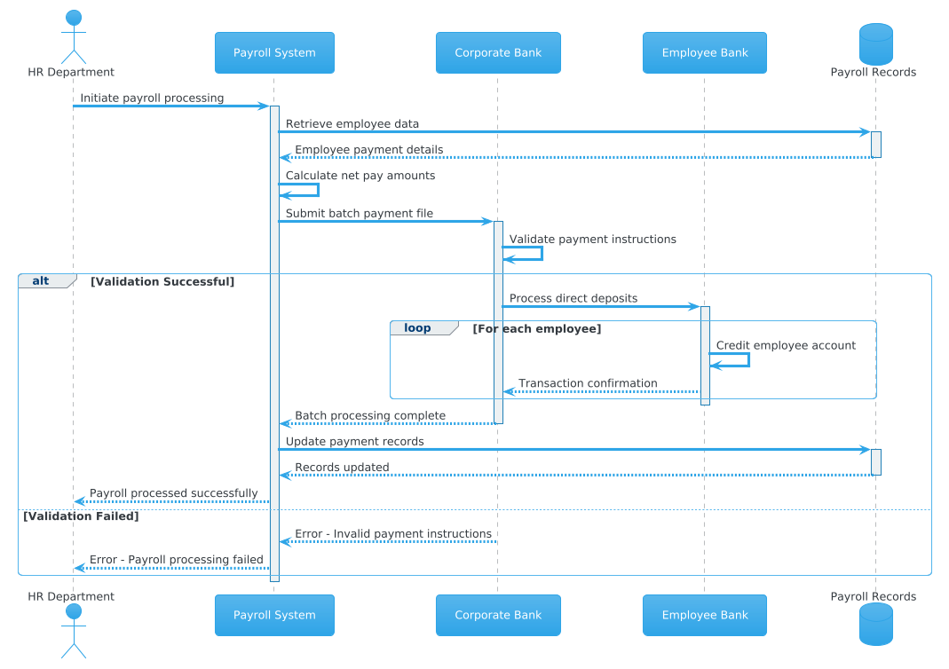
Copy the complete source code below to visualize the diagram instantly in the VPasCode editor.
@startuml
!theme cerulean

actor "HR Department" as HR
participant "Payroll System" as PS
participant "Corporate Bank" as CB
participant "Employee Bank" as EB
database "Payroll Records" as PR

HR -> PS: Initiate payroll processing
activate PS
PS -> PR: Retrieve employee data
activate PR
PR --> PS: Employee payment details
deactivate PR

PS -> PS: Calculate net pay amounts
PS -> CB: Submit batch payment file
activate CB
CB -> CB: Validate payment instructions

alt Validation Successful
    CB -> EB: Process direct deposits
    activate EB

    loop For each employee
        EB -> EB: Credit employee account
        EB --> CB: Transaction confirmation
    end

    deactivate EB
    CB --> PS: Batch processing complete
    deactivate CB

    PS -> PR: Update payment records
    activate PR
    PR --> PS: Records updated
    deactivate PR

    PS --> HR: Payroll processed successfully
else Validation Failed
    CB --> PS: Error - Invalid payment instructions
    deactivate CB
    PS --> HR: Error - Payroll processing failed
end

deactivate PS
@endumlStep-by-Step Architectural Walkthrough
Building this diagram requires a structured approach. We will break down the construction into four logical phases: configuration, entity declaration, flow mapping, and visual polish.
Phase 1: Canvas Configuration & Layout Directives
Before defining any actors, we must set the visual theme and the diagram type. The @startuml directive tells the parser to begin a sequence diagram. We apply the !theme cerulean directive to give the diagram a professional, blue-toned aesthetic that aligns with corporate branding standards.
!theme ceruleanThis single line ensures that all subsequent elements inherit a consistent color palette and border style, reducing the cognitive load on stakeholders reviewing the diagram.
Phase 2: Declaring Core Entities, Actors, and Boundaries
The foundation of the diagram lies in defining the participants. We use specific keywords to denote the nature of each entity:
- Actor: Represents a human role. We define the
HR Departmentas the initiator. - Participant: Represents software systems or services. The
Payroll System,Corporate Bank, andEmployee Bankfall into this category. - Database: Represents persistent storage. The
Payroll Recordsdatabase stores the transaction history.
actor "HR Department" as HR
participant "Payroll System" as PS
participant "Corporate Bank" as CB
Using short aliases (like HR or PS) keeps the message arrows clean and readable, which is crucial when mapping complex financial flows.
Phase 3: Mapping Data Flows & Key Interactions
This is the core logic of the sequence diagram. We map the chronological steps using arrows. Solid arrows indicate synchronous requests, while dashed arrows indicate responses.
We begin with the initiation:
HR -> PS: Initiate payroll processingTo manage visual complexity and indicate when a component is actively working, we use activation bars. This is critical for understanding system load and potential race conditions.
activate PS
PS -> PR: Retrieve employee data
activate PR
We also implement control flow structures. The alt block allows us to model the decision point where the Corporate Bank validates the payment instructions. If validation fails, the else block handles the error path, ensuring the system does not proceed with invalid transactions.
alt Validation Successful
    ... flow ...
else Validation Failed
    ... error flow ...
end
Additionally, the loop directive is used to represent the repetitive action of crediting multiple employee accounts within a single batch, keeping the diagram concise rather than repeating the same steps dozens of times.
Phase 4: Grouping, Annotations & Visual Polish
Finally, we ensure all lifelines are properly deactivated. This indicates that the system is idle and ready for the next transaction. Proper deactivation prevents “leaky” lifelines that might confuse readers about the duration of a process.
deactivate PSThe @enduml directive closes the diagram definition. This structure ensures the diagram renders correctly in the VPasCode editor.
Syntax & Keyword Deep Dive
To master sequence diagrams in PlantUML, you must understand the specific keywords that control the visual representation of your architecture.
actor: Defines a human participant. Use this for roles likeHRorManager.participant: Defines a generic system component. Use this for APIs, microservices, or applications.database: Explicitly marks a storage entity, often styled differently in themes to distinguish it from logic.->(Solid Arrow): Represents a synchronous message or request. The sender waits for a response.-->(Dashed Arrow): Represents a return message or response.activate/deactivate: These keywords draw the vertical activation rectangle on a lifeline, showing when a component is busy.alt/else/end: These create a combined fragment box. Thealt(alternative) block is essential for modeling conditional logic, such as success vs. failure paths.loop: Encapsulates a sequence that repeats. This is vital for batch processing scenarios like payroll.
Best Practices & Pitfalls to Avoid
When building diagrams for finance or enterprise systems, adherence to modeling best practices ensures your documentation remains maintainable and clear.
- Maintain Consistent Abstraction Levels: Do not mix high-level business actors (HR) with low-level technical details (SQL queries) unless necessary. Keep the focus on the interaction boundaries.
- Name Aliases Clearly: While
HRis short, ensure the full name"HR Department"is visible in the diagram to avoid confusion for external stakeholders. - Limit Activation Depth: Avoid nesting too many
activateanddeactivatepairs without breaks, as this can make the diagram look cluttered. Group related activations logically. - Validate Logic Early: Use VPasCode‘s live preview to test your
altandloopblocks immediately. Visual errors in combined fragments are common if theendkeyword is missing.
Start Building PlantUML Sequence Diagrams Faster with VPasCode
Experience instant live browser preview, zero local installation, and interactive syntax testing to visualize your finance workflows today.