


In the high-stakes environment of fintech and online banking, clarity regarding transaction flows is not just a design nicety—it is a critical compliance and security requirement. When a customer initiates a bill payment, a complex orchestration of synchronous and asynchronous messages occurs behind the scenes across multiple microservices, gateways, and ledgers. A well-structured sequence diagram provides the architectural blueprint necessary to validate these interactions before a single line of production code is written.

This tutorial guides you through modeling a Bill Payment Scenario for an Online Banking System using PlantUML within VPasCode. By leveraging the power of diagram-as-code, developers and architects can rapidly prototype these critical workflows, ensuring that error handling, alternative flows, and database interactions are rigorously defined. VPasCode enables you to write this code in your browser, render it instantly, and export it for documentation, all without the need for local Java installations or complex environment configurations.
Understanding the Model: Purpose, Scope & Problem Framing
Diagram Abstraction & Representation
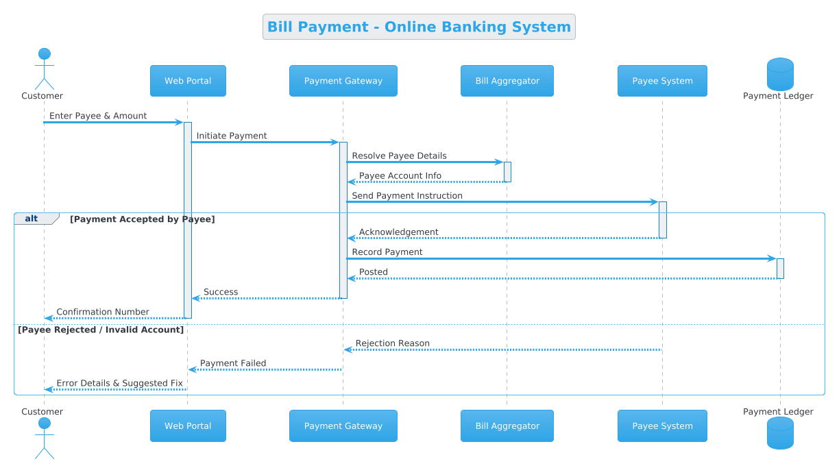
A Sequence Diagram is the industry-standard notation for modeling the dynamic behavior of a system over time. In the context of finance, it maps the temporal ordering of interactions between system components. Unlike static class diagrams, sequence diagrams capture the runtime reality: who sends a message, who receives it, and what happens if a transaction fails. This diagram specifically models the Bill Payment use case, focusing on the message exchange between the user interface (Web Portal), the external payment infrastructure (Gateway), and the backend ledger.
Target Domain Scope & Scenario
The scope of this model is strictly limited to the Payment Initiation and Settlement phases of the online banking lifecycle. It intentionally excludes account balance checks prior to payment (as a prerequisite step) to focus on the core transaction logic. The diagram covers:
- External Actors: The Customer initiating the request.
- Internal Systems: The Web Portal and Payment Ledger.
- External Integrations: The Payment Gateway and the Payee System.
By defining these boundaries, we ensure the diagram remains readable and focused on the critical path of money movement.
Key Takeaways & Educational Insights
By completing this tutorial, you will gain actionable insights into:
- How to model alternative flows (success vs. rejection) using
altandelseblocks. - The distinction between synchronous requests (solid arrows) and asynchronous responses (dashed arrows).
- How to leverage themes like Cerulean to maintain professional branding consistency across your technical documentation.
Complete Diagram & Full Source Code
Below is the complete, rendered blueprint for the Bill Payment sequence diagram. You can view the interactive version directly in the editor below.
@startuml
!theme cerulean

title Bill Payment - Online Banking System

actor Customer
participant "Web Portal" as Portal
participant "Payment Gateway" as Gateway
participant "Bill Aggregator" as Aggregator
participant "Payee System" as Payee
database "Payment Ledger" as PLedger

Customer -> Portal ++ : Enter Payee & Amount
Portal -> Gateway ++ : Initiate Payment
Gateway -> Aggregator ++ : Resolve Payee Details
Aggregator --> Gateway -- : Payee Account Info
Gateway -> Payee ++ : Send Payment Instruction
alt Payment Accepted by Payee
    Payee --> Gateway -- : Acknowledgement
    Gateway -> PLedger ++ : Record Payment
    PLedger --> Gateway -- : Posted
    Gateway --> Portal -- : Success
    Portal --> Customer -- : Confirmation Number
else Payee Rejected / Invalid Account
    Payee --> Gateway -- : Rejection Reason
    Gateway --> Portal -- : Payment Failed
    Portal --> Customer -- : Error Details & Suggested Fix
end

@endumlStep-by-Step Architectural Walkthrough
Phase 1: Canvas Configuration & Layout Directives
Before defining the actors and interactions, we must configure the visual environment. In VPasCode, we start with the @startuml directive, which signals the beginning of the diagram. We then apply the !theme cerulean directive to ensure the diagram adopts a professional, blue-toned aesthetic suitable for financial documentation.
Finally, we define the title to provide immediate context for anyone reviewing the diagram in a documentation suite.
@startuml
!theme cerulean

title Bill Payment - Online Banking System
Phase 2: Declaring Core Entities, Actors, and Boundaries
The foundation of a sequence diagram lies in its lifelines. We declare the participants using specific keywords that define their role in the architecture:
actor Customer: Represents the human user initiating the transaction.participant: Used for software components like theWeb PortalandPayment Gateway.database: Used specifically for thePayment Ledgerto denote persistent storage.
actor Customer
participant "Web Portal" as Portal
participant "Payment Gateway" as Gateway
participant "Bill Aggregator" as Aggregator
participant "Payee System" as Payee
database "Payment Ledger" as PLedger
Phase 3: Mapping Data Flows & Key Interactions
With the actors in place, we map the chronological flow of messages. We use the -> arrow for synchronous requests (where the sender waits for a response) and --> for asynchronous responses.
The initial interaction involves the Customer entering details into the Portal, which triggers the Portal to initiate a payment request to the Gateway. This flow continues through the Aggregator to resolve payee details before reaching the Payee System.
Customer -> Portal ++ : Enter Payee & Amount
Portal -> Gateway ++ : Initiate Payment
Gateway -> Aggregator ++ : Resolve Payee Details
Aggregator --> Gateway -- : Payee Account Info
Gateway -> Payee ++ : Send Payment Instruction
Phase 4: Grouping, Annotations & Visual Polish
Real-world systems must handle both success and failure cases. We use the alt (alternative) and else blocks to encapsulate these conditional flows. The alt block checks if the payment is accepted. If true, the system records the transaction in the ledger. If false (the else block), the system handles the rejection gracefully.
alt Payment Accepted by Payee
    Payee --> Gateway -- : Acknowledgement
    Gateway -> PLedger ++ : Record Payment
    PLedger --> Gateway -- : Posted
    Gateway --> Portal -- : Success
    Portal --> Customer -- : Confirmation Number
else Payee Rejected / Invalid Account
    Payee --> Gateway -- : Rejection Reason
    Gateway --> Portal -- : Payment Failed
    Portal --> Customer -- : Error Details & Suggested Fix
end
Syntax & Keyword Deep Dive
To master PlantUML in VPasCode, understanding the specific syntax for sequence interactions is essential. Below is a breakdown of the key keywords used in this finance workflow diagram.
actor: Defines an external human user who interacts with the system. In this diagram, it represents theCustomer.participant: Defines a system component or service. This is used for theWeb Portal,Gateway, andPayee System.database: A specialized participant type that visually renders a cylinder shape, indicating persistent data storage like thePayment Ledger.->(Solid Arrow): Represents a synchronous message. The sender waits for a response before proceeding. Used forEnter Payee & AmountandInitiate Payment.-->(Dashed Arrow): Represents an asynchronous response or return message. Used forAcknowledgementandSuccessmessages.alt/else/end: These keywords create a combined fragment. They allow you to model branching logic, such as the difference between a successful payment and a rejection.++: This notation is used to indicate that a message is a request that expects a response, visually thickening the arrow line in some renderers to emphasize the call.
Best Practices & Pitfalls to Avoid
When creating sequence diagrams for complex financial systems, adhering to best practices ensures your documentation remains maintainable and readable.
- Keep Diagrams Modular: Do not attempt to model the entire banking system in a single diagram. Focus on specific use cases like Bill Payment or Fund Transfer. This keeps the diagram readable and easier to update.
- Use Meaningful Labels: Always use descriptive text for messages (e.g.,
Enter Payee & Amountinstead ofSend Data). In finance, clarity regarding data payloads is critical for audit trails. - Consistent Naming Conventions: Use aliases (e.g.,
as Portal) to keep message lines concise. This prevents the diagram from becoming cluttered with long component names. - Handle Error Paths Explicitly: Never assume a transaction will always succeed. Always model the
elseblock to show how the system handles rejections, invalid accounts, or timeouts.
Try It Yourself with VPasCode
Start Building PlantUML Diagrams Faster with VPasCode
Design professional sequence diagrams for finance workflows instantly in your browser with zero setup using our free PlantUML editor.