


In the high-stakes domain of finance and insurance, clarity in system requirements is paramount. An Insurance Claims Processing System involves multiple stakeholders, sensitive data flows, and critical decision points that must be validated before payments are released. When architects and business analysts attempt to document these workflows using traditional static diagrams, they often struggle with versioning and maintaining consistency as requirements evolve.
Diagramming-as-code with PlantUML offers a robust solution. By defining your system’s interactions in text, you ensure that your documentation remains a living artifact that can be reviewed, tested, and rendered instantly. Using VPasCode, the free web-based PlantUML editor, you can visualize the boundaries between your system and external actors—such as customers, agents, and third-party fraud detection services—without the overhead of local installation or complex environment setup.
Understanding the Model: Purpose, Scope & Problem Framing
Diagram Abstraction & Representation
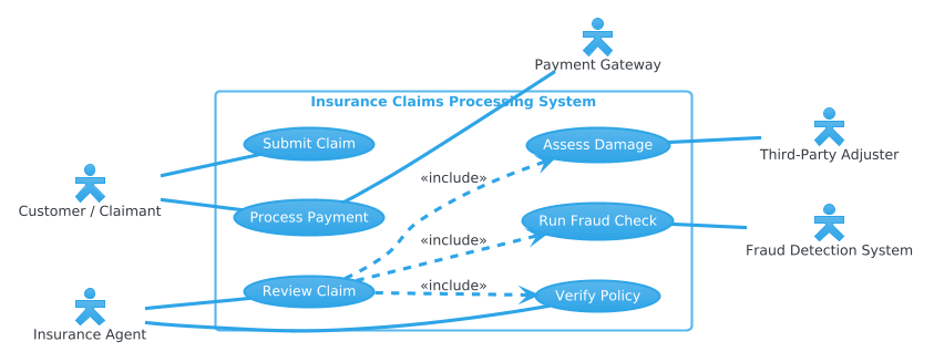
A Use Case diagram is the ideal abstraction for defining system functionality from the user’s perspective. It answers the fundamental question: “What can the system do for whom?” In this model, we represent Actors as external entities (people or systems) that interact with the software. We represent Use Cases as the specific functional goals or tasks the system supports, such as submitting a claim or verifying a policy.
Target Domain Scope & Scenario
This diagram focuses specifically on the core operational workflow of an Insurance Claims Processing System. It intentionally models the boundary between the internal system logic and external dependencies. We include primary actors (Customer, Agent) who initiate processes, and secondary actors (Payment Gateway, Third-Party Adjuster) who assist in completing specific tasks. The scope excludes backend database schemas or internal API endpoints, focusing purely on the functional interaction layer.
Key Takeaways & Educational Insights
By constructing this model, you will gain insights into:
- System Boundaries: Clearly defining what is inside the “Insurance Claims Processing System” versus what remains external.
- Actor Roles: Distinguishing between who initiates a process (Customer) and who validates it (Agent, Adjuster).
- Dependency Logic: Understanding how complex tasks like “Review Claim” depend on simpler sub-tasks like “Verify Policy” or “Run Fraud Check” using include relationships.
Complete Diagram & Full Source Code
Below is the finalized blueprint for the Insurance Claims Processing System. You can view the rendered output immediately by pasting the code below into the VPasCode editor.
@startuml
!theme cerulean
left to right direction

skinparam actorStyle hollow

' Primary Actors (Left)
actor "Customer / Claimant" as Customer
actor "Insurance Agent" as Agent

' System Boundary
rectangle "Insurance Claims Processing System" {
    usecase "Submit Claim" as UC1
    usecase "Review Claim" as UC2
    usecase "Verify Policy" as UC3
    usecase "Assess Damage" as UC4
    usecase "Process Payment" as UC5
    usecase "Run Fraud Check" as UC6
}

' Secondary Actors (Right)
actor "Payment Gateway" as PaymentGateway
actor "Third-Party Adjuster" as Adjuster
actor "Fraud Detection System" as FraudSys

' Connectors without arrowheads
Customer -- UC1
Customer -- UC5
Agent -- UC2
Agent -- UC3

UC4 -- Adjuster
UC5 -- PaymentGateway
UC6 -- FraudSys

' System inclusions
UC2 ..> UC3 : <<include>>
UC2 ..> UC6 : <<include>>
UC2 ..> UC4 : <<include>>
@endumlStep-by-Step Architectural Walkthrough
Building this diagram in VPasCode involves four logical phases. We start with the canvas setup, define the actors and boundaries, map the interactions, and finally polish the visual hierarchy.
Phase 1: Canvas Configuration & Layout Directives
Before defining entities, we set the visual theme and direction. This ensures the diagram looks professional and reads naturally. We use the !theme cerulean directive to apply a clean, modern color palette suitable for financial documentation. The left to right direction directive organizes the flow horizontally, placing actors on the left and right with the system in the center.
!theme cerulean
left to right direction
skinparam actorStyle hollow
Phase 2: Declaring Core Entities, Actors, and Boundaries
Next, we declare the participants. In PlantUML, an actor represents a human or external system. We assign aliases (like Customer) to make referencing them easier later. The rectangle defines the system boundary, encapsulating all internal use cases within the “Insurance Claims Processing System”.
actor "Customer / Claimant" as Customer
actor "Insurance Agent" as Agent

rectangle "Insurance Claims Processing System" {
    usecase "Submit Claim" as UC1
    usecase "Review Claim" as UC2
    usecase "Verify Policy" as UC3
    usecase "Assess Damage" as UC4
    usecase "Process Payment" as UC5
    usecase "Run Fraud Check" as UC6
}
Phase 3: Mapping Data Flows & Key Interactions
With the system boundary established, we connect the actors to their respective tasks. Solid lines -- indicate a direct association. We place secondary actors like the Payment Gateway on the right side to represent external services the system interacts with during specific use cases.
Customer -- UC1
Customer -- UC5
Agent -- UC2
Agent -- UC3

UC4 -- Adjuster
UC5 -- PaymentGateway
UC6 -- FraudSys
Phase 4: Grouping, Annotations & Visual Polish
Finally, we define the internal logic dependencies. The ..> arrow with a <<include<< label indicates that one use case requires another to complete. For example, a Review Claim (UC2) cannot happen without Verify Policy (UC3) and Run Fraud Check (UC6). This creates a logical hierarchy within the diagram.
UC2 ..> UC3 : <>
UC2 ..> UC6 : < >
UC2 ..> UC4 : < > Syntax & Keyword Deep Dive
To master PlantUML in VPasCode, it is essential to understand the specific syntax keywords used in this Insurance Claims model.
actor: Defines a user or external system interacting with the software. Syntax:actor "Name" as Alias.usecase: Represents a specific function or goal within the system. Syntax:usecase "Function Name" as ID.rectangle: Creates a boundary box to group related use cases, visually separating the system from actors.--: The standard association line connecting an actor to a use case or a use case to an external system...>: A dashed arrow used to denote dependencies, such as inclusion or extension relationships between use cases.<<include<<: A stereotype text label indicating that the source use case explicitly incorporates the behavior of the target use case.skinparam: A directive to customize visual styling, such asskinparam actorStyle hollowto change how actors appear.
Best Practices & Pitfalls to Avoid
When modeling financial systems like claims processing, adhere to these guidelines for maintainable diagrams:
- Keep Use Cases Atomic: Avoid combining too many actions into a single use case. For example, keep “Verify Policy” separate from “Review Claim” to allow for clearer dependency mapping.
- Consistent Naming: Use noun phrases for use cases (e.g., “Process Payment” instead of “Process Payments”) to maintain professional consistency.
- Manage Visual Complexity: If the diagram becomes too crowded, consider splitting it into subsystems (e.g., one diagram for Claims Intake, another for Claims Settlement).
- Leverage Themes: Always set a theme early (like
cerulean) to ensure the diagram matches your organization’s branding standards without manual tweaking.
Start Building Insurance Use Case Diagrams Faster with VPasCode
Instantly prototype actor relationships and system boundaries in your browser without installing any tools.