



In the logistics and transportation industry, operational clarity is the backbone of efficiency. A Fleet Management System (FMS) is a complex ecosystem where vehicles, drivers, external tracking services, and maintenance providers must interact seamlessly. However, complex systems often suffer from ambiguous requirements, leading to development delays and operational friction. Visual modeling bridges this gap by translating abstract business processes into concrete architectural blueprints.
This tutorial demonstrates how to construct a professional Use Case Diagram for a Fleet Management System using PlantUML within VPasCode. By leveraging a diagram-as-code approach, architects can maintain living documentation that evolves alongside the system. VPasCode offers an instant, browser-based environment to prototype these models without the overhead of local software installation, allowing teams to focus on architectural logic rather than tool configuration.
Understanding the Model: Purpose, Scope & Problem Framing
Diagram Abstraction & Representation
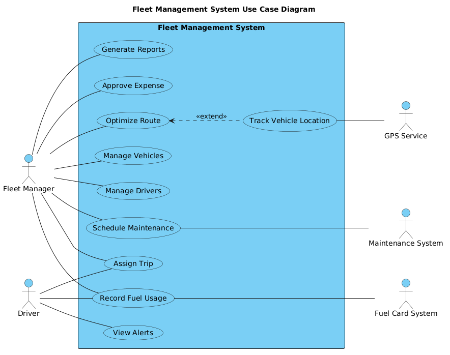
A Use Case Diagram is the primary tool for defining the functional requirements of a system from the perspective of external users. It answers the question: “What can the system do for whom?” In this model, Actors represent the roles interacting with the system (e.g., Fleet Manager, Driver), while Use Cases represent the specific goals or functions they achieve (e.g., Assign Trip, Track Location).
This diagram specifically models the boundary between the internal logic of the Fleet Management System and the external entities that trigger or support its functions. It abstracts away technical implementation details like database schemas or API endpoints, focusing instead on user intent and system responsibility.
Target Domain Scope & Scenario
The scope of this diagram covers the core operational lifecycle of a fleet operator. It includes vehicle lifecycle management, driver assignments, real-time tracking via external GPS, maintenance scheduling, and financial reporting. The model intentionally excludes administrative tasks outside the fleet scope (such as HR payroll) to maintain a clean system boundary.
Key Takeaways & Educational Insights
- Boundary Definition: Learn how to encapsulate use cases within a system rectangle to define scope.
- Actor Classification: Distinguish between primary actors (internal users) and secondary actors (external systems).
- Relationship Mapping: Understand how to model associations and extensions using PlantUML syntax.
Complete Diagram & Full Source Code
Below is the finalized blueprint for the Fleet Management System. You can copy this entire block to use in VPasCode.
@startuml
!include https://static.visual-paradigm.com/web/resources/plantuml-stdlib/themes/vp.puml

title Fleet Management System Use Case Diagram

/'
This diagram illustrates the key functional requirements of a Fleet Management System.
The system is designed to support fleet operators in managing vehicles, drivers,
maintenance schedules, fuel consumption, and trip assignments. Primary actors
represent users who initiate interactions, while secondary actors represent
external systems or entities that provide supporting services or data.
'/

left to right direction

rectangle "Fleet Management System" {
  usecase "Manage Vehicles" as UC1
  usecase "Manage Drivers" as UC2
  usecase "Assign Trip" as UC3
  usecase "Track Vehicle Location" as UC4
  usecase "Schedule Maintenance" as UC5
  usecase "Record Fuel Usage" as UC6
  usecase "Generate Reports" as UC7
  usecase "View Alerts" as UC8
  usecase "Approve Expense" as UC9
  usecase "Optimize Route" as UC10
}

' Primary actors
actor "Fleet Manager" as FM
actor "Driver" as DR

' Secondary actors
actor "GPS Service" as GPS
actor "Maintenance System" as MS
actor "Fuel Card System" as FCS

' Primary actor associations
FM -- UC1
FM -- UC2
FM -- UC3
FM -- UC5
FM -- UC6
FM -- UC7
FM -- UC9
FM -- UC10
DR -- UC3
DR -- UC6
DR -- UC8

' Secondary actor associations
UC4 -- GPS
UC5 --- MS
UC6 --- FCS

' Extended use case
UC10 <.. UC4 : <<extend>>

@endumlStep-by-Step Architectural Walkthrough
Phase 1: Canvas Configuration & Layout Directives
The foundation of any PlantUML diagram lies in its preamble. We begin by including the VPasCode theme to ensure professional styling, followed by the diagram title and a descriptive comment block.
@startuml
!include https://static.visual-paradigm.com/web/resources/plantuml-stdlib/themes/vp.puml

title Fleet Management System Use Case Diagram

/'
This diagram illustrates the key functional requirements...
'/
The left to right direction directive is crucial here. It forces the diagram to render horizontally, which is often more readable for use case diagrams with multiple actors on opposite sides.
Phase 2: Declaring Core Entities, Actors, and Boundaries
We define the system boundary using a rectangle container. Inside this boundary, we declare all use cases. Using aliases (e.g., as UC1) helps keep the code clean when referencing these elements later.
rectangle "Fleet Management System" {
  usecase "Manage Vehicles" as UC1
  usecase "Manage Drivers" as UC2
  usecase "Assign Trip" as UC3
  ...
}
Actors are declared outside the rectangle to signify their position relative to the system. We categorize them into Primary (Fleet Manager, Driver) and Secondary (GPS, Maintenance, Fuel Card) actors.
Phase 3: Mapping Data Flows & Key Interactions
Associations are drawn using the -- syntax. In this diagram, we connect the Fleet Manager (FM) to critical management functions like Manage Vehicles (UC1) and Assign Trip (UC3).
FM -- UC1
FM -- UC2
FM -- UC3
DR -- UC3
Notice how the Driver (DR) also connects to Assign Trip (UC3). This indicates that while the Manager initiates the trip, the Driver is an active participant in the interaction, fulfilling the requirement for multi-role collaboration without cluttering the diagram.
Phase 4: Grouping, Annotations & Visual Polish
Finally, we model the dependencies on external systems. The Track Vehicle Location use case relies on the GPS Service. We also model the extend relationship between Optimize Route and Track Vehicle Location.
UC10 <.. UC4 : <> This syntax indicates that tracking location is an optional behavior that can extend the route optimization process, adding nuance to the system’s logic.
Syntax & Keyword Deep Dive
Understanding the specific PlantUML keywords is essential for mastering diagram-as-code. Here is a breakdown of the syntax used in this Fleet Management diagram:
@startuml/@enduml: The mandatory delimiters that define the start and end of the diagram code block.!include: A directive that loads external style files (themes) to standardize the visual appearance across the organization.title: Sets the main heading displayed above the rendered diagram./' ... '/: Creates a multi-line comment block that provides context for the diagram without rendering visually.rectangle: Defines the system boundary, grouping related use cases together.actor: Declares a user or external system that interacts with the use cases.usecase: Defines a specific function or goal within the system boundary.--: Represents a standard association line between an actor and a use case.<..: Represents a dependency or extension relationship, often used for optional behaviors.
Best Practices & Pitfalls to Avoid
- Maintain System Boundaries: Always ensure use cases inside the rectangle are functional goals, while actors outside are the entities triggering them. Avoid placing system internals (like database tables) inside a Use Case Diagram.
- Use Meaningful Aliases: When defining use cases, assign short aliases (e.g.,
as UC1). This prevents repetitive long names in association lines and makes refactoring easier. - Limit Actor Complexity: Avoid connecting too many actors to a single use case unless it is truly collaborative. Keep the diagram readable by focusing on the primary interaction flows.
- Consistent Naming: Use verb-noun phrases for use cases (e.g., “Manage Vehicles”) rather than nouns (e.g., “Vehicles”) to clearly denote action and intent.
Start Building Fleet Management Diagrams Faster with VPasCode
Visualize your logistics architecture instantly in the browser with zero setup using VPasCode, the free PlantUML editor for professional diagrams.