


In the high-stakes environment of healthcare research, clarity is not just a design preference; it is a regulatory necessity. Clinical trials involve intricate workflows where patient safety, data integrity, and regulatory compliance intersect. A Clinical Trial Management System (CTMS) serves as the digital backbone for these operations, coordinating activities between researchers, patients, and external regulatory bodies.

However, documenting these complex interactions in traditional static diagrams can be time-consuming and prone to version drift. Diagram-as-code offers a superior alternative for software architects and healthcare IT professionals. By using PlantUML within the VPasCode web editor, teams can generate precise, living documentation that stays synchronized with system requirements.
This tutorial leverages VPasCode to build a professional Use Case diagram for a CTMS. We will explore how to define system boundaries, map primary and secondary actors, and establish clear interaction flows without the overhead of local software installation. This approach ensures your architectural documentation remains accessible, version-independent, and instantly renderable across any web browser.
Understanding the Model: Purpose, Scope & Problem Framing
Before diving into the syntax, it is crucial to understand the architectural abstraction we are modeling. A Use Case diagram is not merely a list of features; it is a representation of the system’s functional scope from the perspective of its stakeholders.
Diagram Abstraction & Representation
In the context of a Clinical Trial Management System, the Use Case diagram serves to delineate the “what” of the system rather than the “how.” It answers critical questions regarding system responsibilities:
- Actors: These represent the roles interacting with the system. In healthcare, these are distinct professional roles (e.g., Principal Investigator, Study Coordinator) rather than generic users.
- Use Cases: These encapsulate high-level goals or functions (e.g., Enroll Patient, Report Adverse Event) that provide value to the actors.
- System Boundary: The rectangle defines the scope of the CTMS. Anything inside is part of the software; anything outside is an external entity.
Target Domain Scope & Scenario
This model focuses specifically on the core operational loop of a clinical trial. We intentionally exclude lower-level database interactions or UI wireframes to maintain a high-level architectural view. The diagram covers the lifecycle from trial setup to data submission, ensuring that the critical path for patient safety and regulatory reporting is clearly visualized.
Key Takeaways & Educational Insights
By constructing this diagram, you will gain insights into:
- Stakeholder Analysis: Distinguishing between internal system users (primary actors) and external data sources (secondary actors).
- Boundary Definition: Clearly separating the CTMS from external systems like Lab Systems or Safety Databases.
- Workflow Clarity: Visualizing how data flows between roles and functions to ensure no critical compliance step is overlooked.
Complete Diagram & Full Source Code
Below is the finalized blueprint for the Clinical Trial Management System Use Case diagram. This model utilizes the Rose theme for a clean, professional aesthetic and follows strict PlantUML conventions for actor placement and association.
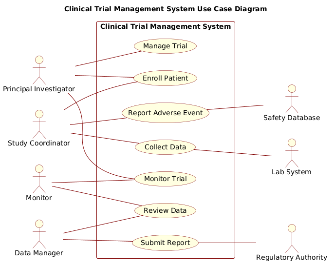
@startuml
!include https://static.visual-paradigm.com/web/resources/plantuml-stdlib/themes/rose.puml

title Clinical Trial Management System Use Case Diagram

/'
  This use case diagram captures the primary functions of a Clinical Trial
  Management System. The system supports clinical research staff in managing
  trial setup, patient enrollment, data collection, safety monitoring, and
  regulatory reporting. Primary actors initiate system interactions, while
  secondary actors represent external entities that the system interfaces with
  during trial execution.
'/

left to right direction

' Primary actors
actor "Principal Investigator" as PI
actor "Study Coordinator" as SC
actor "Data Manager" as DM
actor "Monitor" as Monitor

' Secondary actors
actor "Regulatory Authority" as RA
actor "Safety Database" as SafetyDB
actor "Lab System" as LabSys

rectangle "Clinical Trial Management System" {
  usecase "Manage Trial" as UC1
  usecase "Enroll Patient" as UC2
  usecase "Collect Data" as UC3
  usecase "Report Adverse Event" as UC4
  usecase "Review Data" as UC5
  usecase "Submit Report" as UC6
  usecase "Monitor Trial" as UC7
}

' Primary actors to use cases
PI -- UC1
PI -- UC2
PI -- UC7

SC -- UC2
SC -- UC3
SC -- UC4

DM -- UC5
DM -- UC6

Monitor -- UC5
Monitor -- UC7

' Secondary actors to use cases
UC6 -- RA
UC4 -- SafetyDB
UC3 -- LabSys

@endumlStep-by-Step Architectural Walkthrough
Building a robust diagram-as-code model requires a structured approach. We will construct this CTMS diagram in four distinct phases, ensuring each component is logically placed and semantically accurate.
Phase 1: Canvas Configuration & Layout Directives
The foundation of any PlantUML diagram lies in its configuration. We begin by setting the visual theme and the layout direction to optimize readability for the specific audience.
First, we import the Rose theme to ensure a consistent, professional look that matches enterprise documentation standards:
!include https://static.visual-paradigm.com/web/resources/plantuml-stdlib/themes/rose.pumlNext, we define the title and the diagram direction. For Use Case diagrams, especially those with many actors, a left-to-right flow often reads better than the default top-to-bottom, as it mimics the natural reading order of actors to functions.
title Clinical Trial Management System Use Case Diagram
left to right direction
We also include a comment block to document the context of the diagram. VPasCode renders these comments as text within the diagram, providing immediate context to viewers without cluttering the visual syntax.
/'
  This use case diagram captures the primary functions of a Clinical Trial
  Management System...
'/
Phase 2: Declaring Core Entities, Actors, and Boundaries
With the canvas ready, we declare the actors. In healthcare modeling, precision in naming is vital. We define primary actors (internal users) and secondary actors (external systems) separately.
Primary actors are defined using the actor keyword. We assign aliases (e.g., as PI) to keep association lines clean later.
actor "Principal Investigator" as PI
actor "Study Coordinator" as SC
actor "Data Manager" as DM
actor "Monitor" as Monitor
Secondary actors represent external dependencies. In this CTMS, these include regulatory bodies and external databases.
actor "Regulatory Authority" as RA
actor "Safety Database" as SafetyDB
actor "Lab System" as LabSys
The system boundary is created using the rectangle keyword. This visually encapsulates the use cases, clearly defining what is inside the software scope.
rectangle "Clinical Trial Management System" {
  usecase "Manage Trial" as UC1
  usecase "Enroll Patient" as UC2
  ...
}
Phase 3: Mapping Data Flows & Key Interactions
The core of the Use Case diagram is the relationship between actors and use cases. We use the double-dash operator -- to create associations without arrowheads, as per the specific requirement for this model.
We map the Principal Investigator (PI) to critical management functions:
PI -- UC1
PI -- UC2
PI -- UC7
Similarly, we connect the Study Coordinator (SC) to enrollment and data collection tasks. Note that we avoid multiple primary actors connecting to the same use case unless necessary, maintaining a clean visual hierarchy.
SC -- UC2
SC -- UC3
SC -- UC4
Phase 4: Grouping, Annotations & Visual Polish
Finally, we connect the secondary actors. These associations typically represent data exchange or external triggers. For example, the submission of a report (UC6) connects to the Regulatory Authority (RA).
UC6 -- RA
UC4 -- SafetyDB
UC3 -- LabSys
By placing secondary actors on the right side of the diagram (due to the left to right direction), we create a logical flow from internal actors (left) to external entities (right). This visual separation helps stakeholders quickly identify which parts of the system require external integration.
Syntax & Keyword Deep Dive
To customize and maintain this diagram effectively, understanding the specific PlantUML syntax is essential. Here is a breakdown of the key elements used in this CTMS model.
actor: Defines a participant in the system. Supports aliases (e.g.,as PI) to reference the actor later in association lines.usecase: Defines a specific function or goal within the system boundary. Aliases (e.g.,as UC1) help manage complex association lines.rectangle: Creates a boundary box. Everything enclosed is considered part of the system being modeled.--: Represents a standard association relationship. Unlike sequence diagrams, use case diagrams often use simple lines without arrows to denote interaction./' ... '/: Defines a comment block. Text inside is rendered as a note on the diagram, useful for high-level descriptions or context.title: Sets the main heading for the diagram, ensuring it is identifiable when shared or exported.left to right direction: Forces the layout engine to arrange elements horizontally, which is often better for actor-to-use-case flows.
Best Practices & Pitfalls to Avoid
When modeling healthcare systems with PlantUML, adherence to best practices ensures your diagrams remain maintainable and clear.
- Maintain Clear Boundaries: Do not place external systems inside the
rectangle. Keep the CTMS boundary strict to avoid confusion between internal logic and external integrations. - Consistent Naming Conventions: Use full names for actors (e.g., “Principal Investigator”) in the display text, but use short aliases (e.g.,
as PI) for code references. This keeps the diagram readable but the code concise. - Avoid Over-Complexity: If a diagram becomes too crowded, consider splitting it into sub-diagrams (e.g., one for Enrollment, one for Reporting). Keep the high-level view focused on major goals.
- Validate Association Logic: Ensure every actor has a logical reason to interact with a use case. Avoid “ghost” connections that imply functionality that doesn’t exist in the system.
Start Building Use Case Diagrams Faster with VPasCode
Instantly prototype and visualize your Clinical Trial Management workflows in your browser with VPasCode’s free PlantUML editor. No installation required.