


In the complex landscape of modern financial services, clarity in system requirements is paramount. Factoring and invoice discounting are critical mechanisms where businesses sell their accounts receivable to obtain immediate liquidity. However, these workflows involve multiple stakeholders—sellers, buyers, financial institutions, and system administrators—each with distinct responsibilities and interactions. Without a clear visual model, the boundaries of responsibility can blur, leading to compliance risks or implementation errors.

This tutorial demonstrates how to architect a professional Use Case Diagram for a Factoring and Invoice Discounting System using PlantUML within VPasCode. By adopting a diagram-as-code approach, financial architects and software engineers can maintain a living documentation of system behavior. VPasCode provides an instant browser-based rendering environment, eliminating the need for local Java installations or complex CLI configurations. This allows teams to prototype, validate, and share architectural blueprints rapidly, ensuring all stakeholders understand the functional scope before a single line of production code is written.
Understanding the Model: Purpose, Scope & Problem Framing
Diagram Abstraction & Representation
A Use Case diagram is the primary tool for defining the functional requirements of a system from a user perspective. It models the interaction between external actors and the system itself. In this specific financial context, the diagram abstracts the high-level business goals rather than the technical implementation details.
- Actors: Represent human roles or external systems (e.g., “Client (Seller)” or “Financial Institution (Bank)”). They define who interacts with the system.
- Use Cases: Represent specific functional goals (e.g., “Submit Invoice” or “Disburse Advance Funds”). They define what the system does.
- System Boundary: The rectangle encloses the scope. Anything outside is an external entity; anything inside is part of the software solution.
Target Domain Scope & Scenario
This model focuses on the core operational flow of a factoring platform. It intentionally excludes backend database schemas or API endpoint definitions to maintain focus on user roles and business value. The scope covers the lifecycle from invoice submission by a seller to payment verification by a debtor and fund disbursement by a bank.
Key Takeaways & Educational Insights
By constructing this model, you will gain:
- Boundary Clarity: A definitive view of what is handled by the system versus external actors.
- Stakeholder Mapping: Clear identification of the Client, Admin, Debtor, and Bank roles.
- Requirement Validation: A visual checklist to ensure all critical financial transactions (Credit Assessment, Payment Verification) are accounted for.
Complete Diagram & Full Source Code
Below is the finished blueprint for the Factoring and Invoice Discounting System. You can view the rendered output immediately and interact with the code to customize it.
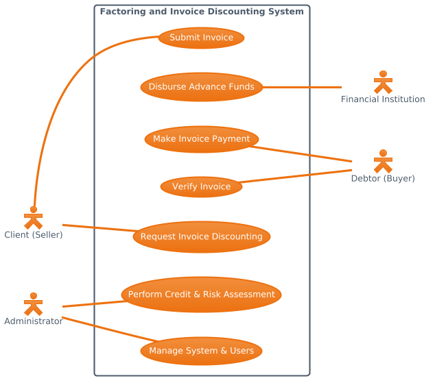
Copy the following complete source code to replicate this diagram.
@startuml
!theme aws-orange
left to right direction

skinparam actorStyle hollow

actor "Client (Seller)" as Client
actor "Administrator" as Admin

actor "Debtor (Buyer)" as Debtor
actor "Financial Institution" as Bank

rectangle "Factoring and Invoice Discounting System" {
    usecase "Submit Invoice" as UC1
    usecase "Request Invoice Discounting" as UC2
    usecase "Perform Credit & Risk Assessment" as UC3
    usecase "Disburse Advance Funds" as UC4
    usecase "Verify Invoice" as UC5
    usecase "Make Invoice Payment" as UC6
    usecase "Manage System & Users" as UC7
}

Client -- UC1
Client -- UC2
Admin -- UC3
Admin -- UC7

UC5 -- Debtor
UC6 -- Debtor
UC4 -- Bank

@endumlStep-by-Step Architectural Walkthrough
Building this diagram in VPasCode involves a logical progression from canvas setup to detailed relationship mapping. Follow these phases to construct your own financial system model.
Phase 1: Canvas Configuration & Layout Directives
Every PlantUML diagram begins with directives that control the rendering engine’s behavior. For financial diagrams, readability is key. We start by defining the theme and the layout direction.
First, we initialize the diagram with @startuml and apply a specific visual theme to match corporate branding. Here, we use the aws-orange theme for a professional, warm tone.
!theme aws-orangeNext, we set the layout direction. Financial workflows often flow logically from left to right (Client to Bank). This directive ensures the diagram renders horizontally rather than the default vertical stack.
left to right directionPhase 2: Declaring Core Entities, Actors, and Boundaries
The next step is defining the participants. In a use case diagram, actors are the external agents interacting with the system. We declare them using the actor keyword and assign them identifiers for referencing later.
We define the internal and external actors involved in the factoring process:
actor "Client (Seller)" as Client
actor "Administrator" as Admin
actor "Debtor (Buyer)" as Debtor
actor "Financial Institution" as Bank
To define the system scope, we use a rectangle to enclose the use cases. This creates the system boundary, visually separating internal logic from external actors.
rectangle "Factoring and Invoice Discounting System" {
    // Use cases go here
}
Phase 3: Mapping Data Flows & Key Interactions
With the actors and boundary in place, we populate the system with its functional goals (Use Cases). Each use case represents a specific transaction or administrative task.
We define the use cases inside the rectangle:
usecase "Submit Invoice" as UC1
usecase "Request Invoice Discounting" as UC2
usecase "Perform Credit & Risk Assessment" as UC3
usecase "Disburse Advance Funds" as UC4
usecase "Verify Invoice" as UC5
usecase "Make Invoice Payment" as UC6
usecase "Manage System & Users" as UC7
Finally, we map the relationships. In PlantUML, the -- symbol represents an association line connecting an actor to a use case. We map the Client to submission tasks, the Admin to risk and management tasks, and the Bank/Debtor to financial settlement tasks.
Client -- UC1
Client -- UC2
Admin -- UC3
Admin -- UC7
UC5 -- Debtor
UC6 -- Debtor
UC4 -- Bank
Phase 4: Grouping, Annotations & Visual Polish
To ensure the diagram looks professional, we apply skin parameters. For this financial model, we want the actors to have a distinct “hollow” style to differentiate them from the system boundary.
skinparam actorStyle hollowThis styling choice enhances visual hierarchy, making it immediately clear who the external users are versus the internal system components.
Syntax & Keyword Deep Dive
Understanding the specific PlantUML syntax features is crucial for building robust diagrams. Below is a breakdown of the keywords used in this financial use case model.
@startuml/@enduml: These delimiters mark the beginning and end of the diagram definition. Without them, the parser cannot identify the diagram scope.!theme: A directive that applies a predefined color palette and style set to the entire diagram. Using!theme aws-orangeensures consistent branding.actor: Defines an external entity interacting with the system. The syntaxactor "Label" as IDallows you to use theIDfor connections later.rectangle: Creates a container box. Anything defined inside this block is considered part of the system boundary.usecase: Defines a specific functional goal. It is enclosed within the system rectangle to indicate it is an internal capability.--: The association operator. It draws a solid line between two elements, indicating a relationship or interaction.skinparam: Used to customize visual attributes likeactorStyle, background colors, or font sizes without changing the logical structure.
Best Practices & Pitfalls to Avoid
When modeling financial systems with VPasCode and PlantUML, adhere to these best practices to ensure your diagrams remain maintainable and clear.
- Maintain Clear Boundaries: Ensure every actor is clearly outside the system rectangle. If an actor is inside the box, it implies they are part of the software logic, which is incorrect for use case diagrams.
- Use Descriptive Naming: Avoid generic names like “User 1”. Use domain-specific names like “Client (Seller)” or “Financial Institution (Bank)” to provide immediate context to stakeholders.
- Limit Scope per Diagram: Do not try to model every single API endpoint in a use case diagram. Stick to high-level business functions. If you need to detail internal logic, use Sequence Diagrams or Class Diagrams instead.
- Consistent Association Direction: While PlantUML allows undirected lines, ensure the flow of interaction makes sense. For example, the Bank should be associated with “Disburse Advance Funds” (UC4), not “Submit Invoice” (UC1).
Try It Yourself with VPasCode
Start Building Financial Use Case Diagrams Faster with VPasCode
Instantly prototype and validate your Factoring System architecture online with VPasCode, the free web-based editor for financial architects.