


In the realm of financial technology, security is not merely a feature but the foundational architecture of trust. When a customer interacts with an Automated Teller Machine (ATM) to change their Personal Identification Number (PIN), a complex chain of synchronous and asynchronous events must occur seamlessly. Any ambiguity in this workflow can lead to security vulnerabilities or user frustration. Visual modeling serves as the blueprint for these critical interactions, ensuring that every component—from the physical card reader to the backend host processor—communicates with precision.

Diagramming-as-code, specifically using PlantUML within the VPasCode web editor, transforms this architectural planning into an agile process. Unlike static drawing tools, VPasCode allows software architects and financial engineers to define system behaviors through text, enabling instant live rendering and version-agnostic documentation. This approach enhances architectural clarity, allowing teams to rapidly prototype, test, and refine complex security protocols without the overhead of local environment setup.
Understanding the Model: Purpose, Scope & Problem Framing
Before diving into the syntax, it is crucial to understand the abstraction and scope of the model we are constructing.
Diagram Abstraction & Representation
A Sequence Diagram is the ideal tool for modeling time-ordered interactions between system components. In this specific scenario, the diagram abstracts the runtime behavior of the ATM system. It maps the temporal flow of messages, showing how the Customer initiates a request, how the ATM Terminal orchestrates hardware inputs (Card Reader, PIN Pad), and how the Host Processor validates credentials against the Customer Database. This visual representation is critical for debugging race conditions and ensuring data integrity during sensitive operations.
Target Domain Scope & Scenario
This diagram focuses strictly on the PIN Change workflow. It does not cover withdrawals or deposits, nor does it model the physical construction of the ATM. The boundaries are defined as follows:
- Actors: The human user (Customer).
- Hardware Interfaces: The ATM Terminal, Card Reader, and PIN Pad.
- Backend Services: Host Processor and Customer Database.
- Logic: Validation of the old PIN and the update of the new PIN.
Key Takeaways & Educational Insights
By mastering this model, you will gain insights into:
- How to structure synchronous vs. asynchronous messaging using PlantUML.
- The importance of modeling error paths (e.g., invalid PIN) alongside success paths.
- How to use combined fragments (
alt) to represent conditional logic in a sequence flow.
Complete Diagram & Full Source Code
Below is the finished blueprint for the ATM PIN Change scenario. You can visualize the complete interaction flow immediately.
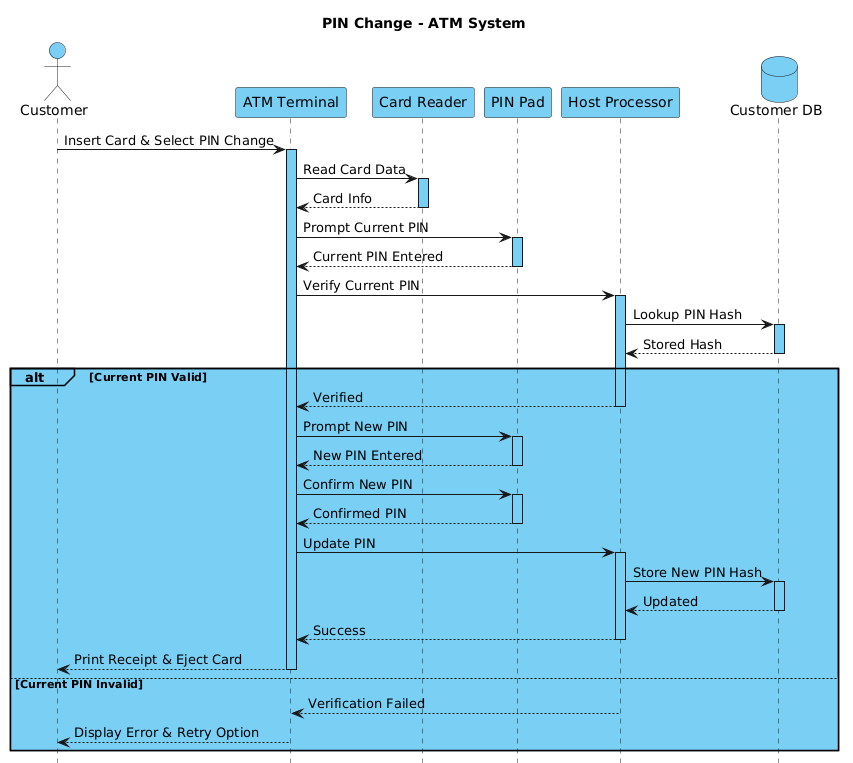
Copy the complete code block below to test it instantly in the VPasCode editor.
@startuml
!include https://static.visual-paradigm.com/web/resources/plantuml-stdlib/themes/vp.puml

title PIN Change - ATM System

actor Customer
participant "ATM Terminal" as ATM
participant "Card Reader" as Card
participant "PIN Pad" as PinPad
participant "Host Processor" as Host
database "Customer DB" as CustDB

Customer -> ATM ++ : Insert Card & Select PIN Change
ATM -> Card ++ : Read Card Data
Card --> ATM -- : Card Info
ATM -> PinPad ++ : Prompt Current PIN
PinPad --> ATM -- : Current PIN Entered
ATM -> Host ++ : Verify Current PIN
Host -> CustDB ++ : Lookup PIN Hash
CustDB --> Host -- : Stored Hash
alt Current PIN Valid
    Host --> ATM -- : Verified
    ATM -> PinPad ++ : Prompt New PIN
    PinPad --> ATM -- : New PIN Entered
    ATM -> PinPad ++ : Confirm New PIN
    PinPad --> ATM -- : Confirmed PIN
    ATM -> Host ++ : Update PIN
    Host -> CustDB ++ : Store New PIN Hash
    CustDB --> Host -- : Updated
    Host --> ATM -- : Success
    ATM --> Customer -- : Print Receipt & Eject Card
else Current PIN Invalid
    Host --> ATM -- : Verification Failed
    ATM --> Customer -- : Display Error & Retry Option
end

@endumlStep-by-Step Architectural Walkthrough
Let us deconstruct this diagram into four logical phases to understand how each component contributes to the secure workflow.
Phase 1: Canvas Configuration & Layout Directives
The first step in any PlantUML sequence diagram is setting the stage. We begin with the @startuml directive to initialize the diagram. Crucially, we include the VPasCode theme to ensure the visual output matches modern UI standards.
Here is the setup code:
@startuml
!include https://static.visual-paradigm.com/web/resources/plantuml-stdlib/themes/vp.puml

title PIN Change - ATM System
The title directive provides context for anyone viewing the rendered diagram, ensuring clarity on what process is being modeled.
Phase 2: Declaring Core Entities, Actors, and Boundaries
Next, we define the participants. In PlantUML, different types of participants can be declared to represent different architectural layers. We use actor for humans, participant for software or hardware interfaces, and database for data stores.
actor Customer
participant "ATM Terminal" as ATM
participant "Card Reader" as Card
participant "PIN Pad" as PinPad
participant "Host Processor" as Host
database "Customer DB" as CustDB
Using aliases (e.g., as ATM) allows us to reference these entities concisely in the interaction flow later, keeping the diagram readable.
Phase 3: Mapping Data Flows & Key Interactions
This phase covers the initial interaction sequence. We use arrows to denote messages. The ++ modifier indicates a synchronous call (blocking), while -- indicates a return message.
Customer -> ATM ++ : Insert Card & Select PIN Change
ATM -> Card ++ : Read Card Data
Card --> ATM -- : Card Info
Notice how the flow moves from the user to the terminal, then to the hardware reader, and back. This establishes the context before any security verification occurs.
Phase 4: Grouping, Annotations & Visual Polish
Complex workflows rarely follow a single straight line. We must account for failure scenarios. The alt (alternative) combined fragment allows us to group logic based on conditions.
alt Current PIN Valid
    [Success Path Code Here]
else Current PIN Invalid
    [Error Path Code Here]
end
This structure ensures that the diagram explicitly documents what happens when the host processor verifies the PIN hash against the database. It prevents ambiguity in the system requirements.
Syntax & Keyword Deep Dive
Understanding the specific PlantUML syntax is key to mastering VPasCode. Here is a breakdown of the critical keywords used in this diagram.
actor: Defines a human user or external system interacting with the diagram.participant: Represents a software component, class, or hardware interface.database: Specifically styles a lifeline as a data store, distinct from a standard participant.->vs-->:->denotes a request or message sent.-->denotes the return response.++: Indicates a synchronous message where the sender waits for a response before proceeding.alt/else/end: These keywords create a combined fragment box.altstarts the alternative group,elsedefines the fallback condition, andendcloses the block.
Best Practices & Pitfalls to Avoid
To maintain professional quality in your diagrams using VPasCode, adhere to these modeling guidelines:
- Maintain Logical Grouping: Always use
alt,opt, orloopfragments to separate distinct logical paths. Avoid spaghetti-like flows that cross without boundaries. - Clear Naming Conventions: Use descriptive labels for messages (e.g.,
Verify Current PINinstead ofCheck). This makes the diagram self-documenting for stakeholders. - Consistent Arrow Types: Decide on a standard for synchronous vs. asynchronous messages and stick to it throughout the diagram to avoid confusion.
- Limit Scope: Do not try to model every possible system event in one diagram. Focus on specific use cases like PIN Change to keep the diagram readable.
Try It Yourself with VPasCode
Start Building PlantUML Sequence Diagrams Faster with VPasCode
Test, preview, and customize your ATM workflow diagrams instantly in your browser with VPasCode, the free web-based diagram editor.