


In the rapidly evolving landscape of fintech, digital wallets have become the backbone of modern financial transactions. Whether facilitating peer-to-peer transfers, enabling merchant payments, or managing personal assets, the architecture behind these systems must be robust, secure, and user-centric. For software architects and product designers, visualizing these complex interactions is not just a documentation exercise—it is a critical step in defining system boundaries and user expectations.

Traditional drag-and-drop diagramming tools often lack the precision and versioning capabilities required for rigorous system modeling. Diagram-as-code approaches, specifically using PlantUML, offer a superior alternative. By defining your architecture through text, you ensure consistency, reduce visual clutter, and allow for rapid iteration. In this masterclass, we utilize VPasCode, the free web-based diagram-as-code editor, to construct a comprehensive Use Case Diagram for a Digital Wallet System. This approach enhances architectural clarity, supports rapid visual prototyping, and serves as living technical documentation that evolves with your codebase.
Understanding the Model: Purpose, Scope & Problem Framing
Before writing a single line of code, it is essential to understand the abstraction and domain scope of the model we are building. A Use Case Diagram is the primary tool for capturing the functional requirements of a system from the perspective of external actors.
Diagram Abstraction & Representation
In the context of a Digital Wallet, this diagram models the “what” of the system rather than the “how”. It defines the functional goals (Use Cases) and the roles (Actors) that interact with them. Unlike Sequence Diagrams which focus on runtime messaging, or Class Diagrams which focus on data structures, the Use Case Diagram focuses on high-level business functionality. It answers critical questions: Who can access the wallet? What actions are they permitted to perform? Where does the system boundary lie?
Target Domain Scope & Scenario
This model covers the core ecosystem of a digital payment platform. We define four primary actors:
- Customer: The primary user managing personal funds.
- Merchant: The business entity accepting payments.
- Bank System: The external financial infrastructure handling fund movement.
- Admin: The internal operator managing security and user governance.
The system boundary encompasses all transactional capabilities, from onboarding to fraud monitoring, excluding the internal implementation details of the banking API.
Key Takeaways & Educational Insights
By the end of this tutorial, you will gain insights into how to:
- Define clear system boundaries using PlantUML rectangles.
- Map complex multi-party interactions without visual clutter.
- Structure financial workflows using standard diagram-as-code conventions.
- Leverage VPasCode for instant browser-based rendering without local setup.
Complete Diagram & Full Source Code
Below is the finished blueprint for the Digital Wallet System. This diagram encapsulates the registration, funding, transaction, and administrative workflows within a single, cohesive view.
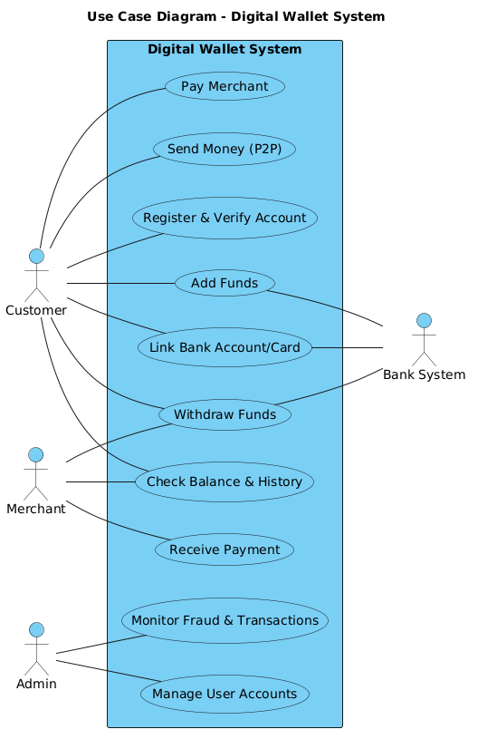
The following source code represents the complete PlantUML definition. You can copy this directly into the VPasCode editor to render the diagram instantly.
@startuml
!include https://static.visual-paradigm.com/web/resources/plantuml-stdlib/themes/vp.puml

title Use Case Diagram - Digital Wallet System

left to right direction

actor "Customer" as customer
actor "Merchant" as merchant
actor "Bank System" as bank
actor "Admin" as admin

rectangle "Digital Wallet System" {
    usecase "Register & Verify Account" as UC_register
    usecase "Link Bank Account/Card" as UC_link
    usecase "Add Funds" as UC_add_funds
    usecase "Check Balance & History" as UC_balance
    usecase "Send Money (P2P)" as UC_send_money
    usecase "Pay Merchant" as UC_pay_merchant
    usecase "Receive Payment" as UC_receive_pay
    usecase "Withdraw Funds" as UC_withdraw
    usecase "Manage User Accounts" as UC_manage_users
    usecase "Monitor Fraud & Transactions" as UC_monitor
}

' Customer Relations
customer -- UC_register
customer -- UC_link
customer -- UC_add_funds
customer -- UC_balance
customer -- UC_send_money
customer -- UC_pay_merchant
customer -- UC_withdraw

' Merchant Relations
merchant -- UC_balance
merchant -- UC_receive_pay
merchant -- UC_withdraw

' Bank Relations
UC_link -- bank
UC_add_funds -- bank
UC_withdraw -- bank

' Admin Relations
admin -- UC_manage_users
admin -- UC_monitor

@endumlStep-by-Step Architectural Walkthrough
Building a professional diagram requires a structured approach. We will deconstruct the code into four logical phases to ensure you understand the architectural intent behind every line.
Phase 1: Canvas Configuration & Layout Directives
The first step is setting the stage. We begin by including the VPasCode theme to ensure consistent styling across the diagram. We also define the layout direction to optimize readability for wide-screen displays.
@startuml
!include https://static.visual-paradigm.com/web/resources/plantuml-stdlib/themes/vp.puml

title Use Case Diagram - Digital Wallet System

left to right direction
The left to right direction directive ensures the diagram flows horizontally, which is ideal for Use Case Diagrams that often span wide actor relationships.
Phase 2: Declaring Core Entities, Actors, and Boundaries
Next, we define the external actors who interact with the system. In PlantUML, actors are declared using the actor keyword. We assign aliases (like as customer) to make referencing them easier in later relationship definitions.
actor "Customer" as customer
actor "Merchant" as merchant
actor "Bank System" as bank
actor "Admin" as admin
Following the actors, we establish the system boundary using a rectangle. This visual container defines the scope of the Digital Wallet System. Any use case inside this rectangle is a function provided by the system itself.
rectangle "Digital Wallet System" {
    usecase "Register & Verify Account" as UC_register
    usecase "Link Bank Account/Card" as UC_link
    usecase "Add Funds" as UC_add_funds
    usecase "Check Balance & History" as UC_balance
    usecase "Send Money (P2P)" as UC_send_money
    usecase "Pay Merchant" as UC_pay_merchant
    usecase "Receive Payment" as UC_receive_pay
    usecase "Withdraw Funds" as UC_withdraw
    usecase "Manage User Accounts" as UC_manage_users
    usecase "Monitor Fraud & Transactions" as UC_monitor
}
Phase 3: Mapping Data Flows & Key Interactions
With actors and use cases declared, we now map the interactions. Relationships are drawn using the -- syntax. This creates a solid line connecting the actor to the use case, indicating an association.
' Customer Relations
customer -- UC_register
customer -- UC_link
customer -- UC_add_funds
customer -- UC_balance
customer -- UC_send_money
customer -- UC_pay_merchant
customer -- UC_withdraw
We repeat this pattern for Merchants, who primarily interact with balance checks, receiving payments, and withdrawals. Notice how the Bank System actor connects to specific use cases (Link, Add Funds, Withdraw) rather than the entire system. This accurately models that the bank is an external dependency triggered by specific financial actions.
Phase 4: Grouping, Annotations & Visual Polish
Finally, we ensure the Admin role is correctly positioned. The Admin does not perform transactions but manages the system integrity. This is represented by linking the Admin to user management and fraud monitoring.
' Admin Relations
admin -- UC_manage_users
admin -- UC_monitor
By grouping these relationships logically in the code, we maintain readability. VPasCode renders these connections instantly, allowing you to verify the flow before exporting.
Syntax & Keyword Deep Dive
Understanding the specific PlantUML syntax features used in this diagram is crucial for extending the model in the future. Here is a breakdown of the key keywords:
actor: Defines a human or external system interacting with the primary system. In this diagram, it represents roles likeCustomerorBank System.usecase: Defines a specific functional goal or action available within the system boundary. Eachusecaseblock represents a distinct capability.rectangle: Creates a visual boundary box. This is critical for defining the system scope, separating internal functionality from external actors.--: The association operator. It draws a solid line between two elements, indicating a direct interaction or relationship.left to right direction: A layout directive that forces the diagram rendering engine to organize elements horizontally rather than vertically.!include: Allows importing external libraries or themes. Here, it loads the VPasCode standard library for consistent styling.
Best Practices & Pitfalls to Avoid
To maintain high-quality architectural documentation, adhere to these modeling best practices when using VPasCode:
- Maintain System Boundaries: Ensure all actors outside the
rectanglerepresent external entities. Internal processes should not be exposed as actors unless they are external services. - Use Descriptive Aliases: Always assign aliases (e.g.,
as customer) to actors and use cases. This prevents syntax errors when drawing multiple connections and improves code readability. - Group Related Use Cases: When a system grows, use the
rectangleto group related functionalities (e.g., “Payment Processing” vs. “User Management”) to reduce visual clutter. - Avoid Over-Abstraction: Ensure every use case represents a meaningful goal for an actor. If a use case has no actor connected to it, it may be redundant.
Start Building Digital Wallet Use Case Diagrams Faster with VPasCode
Model complex financial system interactions instantly in your browser with VPasCode, our free PlantUML editor. No installation required.