


In the fast-paced retail industry, visibility into the supply chain is no longer optional—it is a competitive imperative. Modern retail operations rely on complex interactions between internal stakeholders like warehouse managers and external systems like supplier portals. Without a clear visual model of these interactions, requirements often become fragmented, leading to integration errors and operational bottlenecks.
This tutorial demonstrates how to architect a robust Retail Supply Chain Tracking system using PlantUML within VPasCode. By leveraging diagram-as-code practices, you can create living documentation that evolves with your project. VPasCode allows you to write code and see the resulting Use Case diagram instantly in the browser, ensuring your architecture is clear before a single line of application code is written.
Understanding the Model: Purpose, Scope & Problem Framing
Diagram Abstraction & Representation
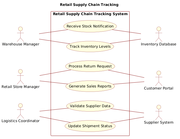
A Use Case diagram serves as a high-level blueprint for system functionality. In this specific context, it maps the what of the system rather than the how. It identifies Actors (the roles interacting with the system) and Use Cases (the specific goals they achieve). For a retail supply chain, this abstraction is critical because it separates business roles from technical implementation details, ensuring all stakeholders agree on the system’s scope.
Target Domain Scope & Scenario
This model focuses on the Retail Supply Chain Tracking System. The scope is intentionally bounded to cover three primary operational pillars:
- Inventory Management: Monitoring stock levels and receiving notifications.
- Shipment Logistics: Updating status and validating supplier data.
- Customer Engagement: Generating reports and processing returns.
By defining this boundary, we ensure that external dependencies (like the Supplier System or Customer Portal) are treated as black boxes interacting with the core system, rather than being modeled as internal processes.
Key Takeaways & Educational Insights
By following this guide, you will gain architectural clarity on:
- How to distinguish between internal human actors and external system actors.
- How to properly group functionality within a system boundary rectangle.
- How to maintain clean associations without over-complicating the visual flow.
Complete Diagram & Full Source Code
Below is the complete PlantUML source code for the Retail Supply Chain Tracking Use Case diagram. You can copy this code directly into the VPasCode editor to render it instantly.
@startuml
title Retail Supply Chain Tracking
/' This diagram illustrates the interactions between actors and the Retail Supply Chain Tracking System, focusing on monitoring inventory, managing shipments, and reporting analytics within the retail environment. '/
!include https://static.visual-paradigm.com/web/resources/plantuml-stdlib/themes/rose.puml

left to right direction

actor "Warehouse Manager" as WM
actor "Retail Store Manager" as RSM
actor "Logistics Coordinator" as LC

actor "Supplier System" as SS
actor "Customer Portal" as CP
actor "Inventory Database" as IDB

rectangle "Retail Supply Chain Tracking System" {
    usecase "Track Inventory Levels" as UC1
    usecase "Update Shipment Status" as UC2
    usecase "Generate Sales Reports" as UC3
    usecase "Receive Stock Notification" as UC4
    usecase "Process Return Request" as UC5
    usecase "Validate Supplier Data" as UC6
}

WM -- UC1
LC -- UC2
RSM -- UC3
WM -- UC4
RSM -- UC5
LC -- UC6

UC1 -- IDB
UC2 -- SS
UC3 -- CP
UC4 -- IDB
UC5 -- CP
UC6 -- SS
@endumlStep-by-Step Architectural Walkthrough
Phase 1: Canvas Configuration & Layout Directives
Every PlantUML diagram begins with configuration. In this phase, we set the visual theme and the reading direction to match modern UI standards.
We start by defining the @startuml directive and the diagram Title. The title is crucial for documentation, ensuring anyone viewing the diagram understands its context immediately. We also include a comment block using /\' and /' to describe the diagram’s purpose without cluttering the rendering.
Next, we apply the Rose theme. This theme provides a professional, clean aesthetic suitable for enterprise documentation. Finally, we set the direction to left to right, which is standard for modern flowcharts and diagrams.
@startuml
title Retail Supply Chain Tracking
/' This diagram illustrates the interactions... '/
!include https://static.visual-paradigm.com/web/resources/plantuml-stdlib/themes/rose.puml
left to right direction
Phase 2: Declaring Core Entities, Actors, and Boundaries
In Use Case modeling, actors represent the users or systems interacting with the software. We distinguish between Primary Actors (internal roles) and Secondary Actors (external systems).
We define three internal roles: Warehouse Manager, Retail Store Manager, and Logistics Coordinator. These are the human users driving the business processes. We then define three external dependencies: Supplier System, Customer Portal, and Inventory Database. These represent systems outside the immediate scope that the application must communicate with.
actor "Warehouse Manager" as WM
actor "Retail Store Manager" as RSM
actor "Logistics Coordinator" as LC

actor "Supplier System" as SS
actor "Customer Portal" as CP
actor "Inventory Database" as IDB
Phase 3: Mapping Data Flows & Key Interactions
With actors defined, we declare the functionality within the system boundary. We use a rectangle to encapsulate the Use Cases belonging to the Retail Supply Chain Tracking System.
Inside the boundary, we map six key interactions: Tracking Inventory, Updating Shipment Status, Generating Sales Reports, Receiving Stock Notifications, Processing Returns, and Validating Supplier Data. Each use case is assigned a unique alias (e.g., UC1) for easier reference in relationship definitions.
rectangle "Retail Supply Chain Tracking System" {
    usecase "Track Inventory Levels" as UC1
    usecase "Update Shipment Status" as UC2
    usecase "Generate Sales Reports" as UC3
    usecase "Receive Stock Notification" as UC4
    usecase "Process Return Request" as UC5
    usecase "Validate Supplier Data" as UC6