


In the rapidly evolving landscape of EdTech, clarity in system requirements is paramount. A Learning Management System (LMS) serves as the digital backbone for educational institutions, connecting students, instructors, and administrators in a complex web of interactions. Without a clear visual representation of these interactions, development teams often face scope creep, misunderstood requirements, and fragmented user experiences.
Use case diagrams are the ideal tool for capturing this functional scope. They provide a high-level view of the system’s capabilities from the perspective of its users. By modeling these interactions using diagram-as-code with PlantUML in VPasCode, architects can achieve rapid prototyping, instant browser-based rendering, and living technical documentation without the friction of traditional GUI modeling tools.
This tutorial demonstrates how to construct a professional-grade LMS use case diagram. We will leverage VPasCode to visualize the boundaries between internal system functions and external integrations, ensuring every stakeholder—from developers to school administrators—shares a unified understanding of the platform’s capabilities.
Understanding the Model: Purpose, Scope & Problem Framing
Diagram Abstraction & Representation
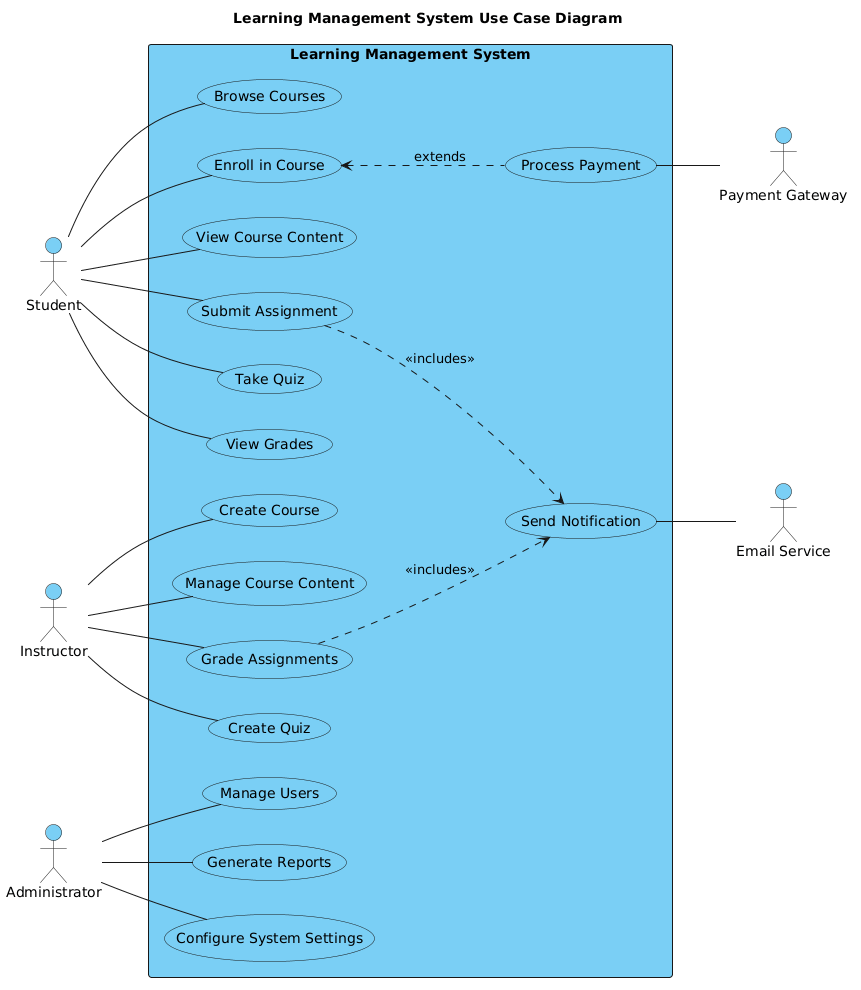
A use case diagram is not merely a list of features; it is a structural abstraction of user-system interactions. In this context, actors represent the distinct roles (Student, Instructor, Administrator) that initiate actions. Use cases represent the specific functional goals achieved within the system boundary (e.g., “Submit Assignment”, “Grade Assignments”).
Crucially, this diagram distinguishes between primary actors who directly interact with the system and secondary actors (external systems) that support specific functions. This separation helps identify dependencies and integration points early in the design phase.
Target Domain Scope & Scenario
The scope of this model covers the core operational lifecycle of an LMS. It intentionally excludes low-level technical details like database schema or API endpoints, focusing instead on the what rather than the how. The diagram defines the system boundary as the “Learning Management System” rectangle, encapsulating all internal logic while exposing interfaces to external services like Payment Gateways and Email Services.
Key Takeaways & Educational Insights
By completing this tutorial, you will gain the ability to:
- Define clear system boundaries to prevent scope creep.
- Map complex relationships including
extendsandincludesscenarios. - Integrate external dependencies (secondary actors) without cluttering the core user flow.
- Utilize VPasCode for instant visual feedback on diagram syntax.
Complete Diagram & Full Source Code
Below is the complete blueprint for the Learning Management System use case diagram. You can view the rendered result immediately using the interactive editor powered by VPasCode.
@startuml
!include https://static.visual-paradigm.com/web/resources/plantuml-stdlib/themes/vp.puml

title Learning Management System Use Case Diagram

/'
This diagram illustrates the core functionalities of a Learning Management System (LMS)
that facilitates online education and training. The system enables students to access
course materials, submit assignments, and track their progress, while instructors can
create courses, manage content, and evaluate student performance. Administrators oversee
the entire platform, managing users and system configurations. External systems such as
payment gateways and notification services integrate with the LMS to support financial
transactions and communication features.
'/

left to right direction

actor "Student" as Student
actor "Instructor" as Instructor
actor "Administrator" as Administrator

rectangle "Learning Management System" {
    usecase "Browse Courses" as UC_BrowseCourses
    usecase "Enroll in Course" as UC_EnrollCourse
    usecase "View Course Content" as UC_ViewContent
    usecase "Submit Assignment" as UC_SubmitAssignment
    usecase "Take Quiz" as UC_TakeQuiz
    usecase "View Grades" as UC_ViewGrades
    usecase "Create Course" as UC_CreateCourse
    usecase "Manage Course Content" as UC_ManageContent
    usecase "Grade Assignments" as UC_GradeAssignments
    usecase "Create Quiz" as UC_CreateQuiz
    usecase "Manage Users" as UC_ManageUsers
    usecase "Generate Reports" as UC_GenerateReports
    usecase "Configure System Settings" as UC_ConfigureSettings
    usecase "Process Payment" as UC_ProcessPayment
    usecase "Send Notification" as UC_SendNotification
}

actor "Payment Gateway" as PaymentGateway
actor "Email Service" as EmailService

' Primary actors on the left
Student -- UC_BrowseCourses
Student -- UC_EnrollCourse
Student -- UC_ViewContent
Student -- UC_SubmitAssignment
Student -- UC_TakeQuiz
Student -- UC_ViewGrades

Instructor -- UC_CreateCourse
Instructor -- UC_ManageContent
Instructor -- UC_GradeAssignments
Instructor -- UC_CreateQuiz

Administrator -- UC_ManageUsers
Administrator -- UC_GenerateReports
Administrator -- UC_ConfigureSettings

' Extend relationship
UC_EnrollCourse <.. UC_ProcessPayment : extends

' Secondary actors on the right
UC_ProcessPayment -- PaymentGateway
UC_SendNotification -- EmailService

' Shared use cases with secondary actor
UC_SubmitAssignment ..> UC_SendNotification : <<includes>>
UC_GradeAssignments ..> UC_SendNotification : <<includes>>

@endumlStep-by-Step Architectural Walkthrough
Phase 1: Canvas Configuration & Layout Directives
Before defining actors, we must configure the canvas to ensure readability. In VPasCode, we start by including the standard library theme to apply a professional visual style automatically.
We then set the layout direction. While use case diagrams often default to vertical, a horizontal flow often works better for LMS diagrams with many actors.
!include https://static.visual-paradigm.com/web/resources/plantuml-stdlib/themes/vp.puml

title Learning Management System Use Case Diagram

/'
This diagram illustrates the core functionalities of a Learning Management System (LMS)
that facilitates online education and training...
'/

left to right direction
The title directive provides a header for the diagram, while the comment block (wrapped in /' and '/) serves as internal documentation visible to developers but not rendered as a graphical element.
Phase 2: Declaring Core Entities, Actors, and Boundaries
Next, we define the human actors and the system boundary. The system boundary is represented by a rectangle that encapsulates all internal use cases.
actor "Student" as Student
actor "Instructor" as Instructor
actor "Administrator" as Administrator

rectangle "Learning Management System" {
    usecase "Browse Courses" as UC_BrowseCourses
    usecase "Enroll in Course" as UC_EnrollCourse
    ...
}
Here, we assign unique aliases (e.g., as Student) to simplify referencing in relationship lines later. The rectangle block ensures that all usecase definitions inside it are logically grouped within the system boundary.
Phase 3: Mapping Data Flows & Key Interactions
With entities defined, we establish the associations. In PlantUML, a solid line with no arrowheads (--) represents a standard association between an actor and a use case.
Student -- UC_BrowseCourses
Student -- UC_EnrollCourse

Instructor -- UC_CreateCourse
Instructor -- UC_ManageContent

Administrator -- UC_ManageUsers
We also introduce conditional logic using the extends relationship. For example, enrolling in a course may require payment. This is modeled as:
UC_EnrollCourse <.. UC_ProcessPayment : extends
The <.. arrow indicates the extension point, and the label extends clarifies the dependency.
Phase 4: Grouping, Annotations & Visual Polish
Finally, we incorporate secondary actors (external systems) and shared behaviors. External systems like Payment Gateways interact with specific use cases rather than primary users.
UC_ProcessPayment -- PaymentGateway
UC_SendNotification -- EmailService

UC_SubmitAssignment ..> UC_SendNotification : <>
The <<includes>> stereotype indicates that submitting an assignment *must* trigger a notification. This modular approach keeps the diagram clean while defining critical business rules.
Syntax & Keyword Deep Dive
To master diagram-as-code, you must understand the specific keywords that drive the rendering engine in VPasCode. Below is a breakdown of the essential syntax used in this LMS diagram.
actor: Defines a user or external system interacting with the diagram. Syntax:actor "Name" as Alias.rectangle: Creates a boundary box to group related use cases, defining the system scope.usecase: Defines a specific functional goal or interaction point within the system boundary.--: Represents a standard association line with no arrowheads, indicating a bidirectional or unweighted relationship.<..: Represents a directed relationship, commonly used forextendsorincludesdependencies.<<stereotype>>: Wraps keywords in double angle brackets to denote specific relationship types like<<includes>>.title: Sets the main heading displayed at the top of the rendered diagram./' ... '/: Defines a multi-line comment block that appears in the diagram metadata but does not render as a visual box.
Best Practices & Pitfalls to Avoid
When building diagrams with VPasCode, adhering to modeling conventions ensures your documentation remains maintainable and scalable.
- Keep Diagrams Modular: Avoid creating a single massive diagram for an entire enterprise system. Split diagrams by domain (e.g., one for "Student Portal", another for "Admin Dashboard").
- Consistent Naming Conventions: Use aliases (e.g.,
as Student) consistently. It reduces errors when drawing lines and makes code easier to read. - Manage Visual Complexity: If a diagram becomes too crowded, consider using
packageor nestedrectanglestructures to group related use cases logically. - Separate Internal vs. External: Clearly distinguish between human actors and external system integrations (like Payment Gateways) to avoid confusion about who initiates the action.
Start Building PlantUML Use Case Diagrams Faster with VPasCode
Model your Learning Management System requirements instantly in your browser with VPasCode, the free PlantUML editor that requires zero local installation.