


In modern retail operations, maintaining accurate inventory visibility across multiple sales channels is a critical architectural challenge. An omnichannel strategy requires seamless synchronization between physical Point-of-Sale (POS) systems, online e-commerce storefronts, and third-party marketplaces. Without a robust synchronization workflow, businesses risk overselling products, damaging customer trust, and disrupting supply chain logistics.

Visual modeling plays a pivotal role in designing these complex systems. By using diagramming-as-code with PlantUML within VPasCode, software architects can rapidly prototype and document the temporal flows of data between services. This approach enhances architectural clarity, allowing teams to validate edge cases like out-of-stock scenarios before writing a single line of backend code. VPasCode serves as an instant, browser-based diagram-as-code tool, enabling engineers to write code and preview diagrams in real time without any local environment setup.
Understanding the Model: Purpose, Scope & Problem Framing
Diagram Abstraction & Representation
A sequence diagram is the ideal visualization tool for this problem because it emphasizes the time-ordered interaction between system components. In this model, lifelines represent active participants (actors and services), while horizontal arrows depict the flow of messages or data requests. Vertical activation bars indicate the period during which a participant is actively processing a request.
For retail inventory management, this abstraction allows architects to map the exact sequence of events: from a customer initiating a purchase, to the validation of stock availability, and finally to the propagation of updates across different channels.
Target Domain Scope & Scenario
This diagram focuses specifically on the inventory synchronization workflow within a Retail Management System. The scope includes:
- Actors: The Customer initiating the transaction.
- Frontend Interfaces: POS terminals or Web Checkout systems.
- Core Services: Order Service and Inventory Service.
- Data Stores: The Central Inventory Database.
- External Integrations: Channel Adapters for Online/Marketplace and Store Systems.
Dependencies are modeled to show how the Order Service relies on the Inventory Service, which in turn interacts with the database and external channels.
Key Takeaways & Educational Insights
By studying this model, readers will gain insights into:
- How to structure synchronous vs. asynchronous messaging in a service-oriented architecture.
- How to model alternative business logic using
altblocks (e.g., success vs. out-of-stock). - How to represent parallel processing using
parblocks for simultaneous channel updates. - Best practices for naming conventions and visual grouping in PlantUML.
Complete Diagram & Full Source Code
Below is the finalized blueprint for the Omnichannel Inventory Synchronization Workflow. You can view the rendered diagram immediately using the interactive editor below.
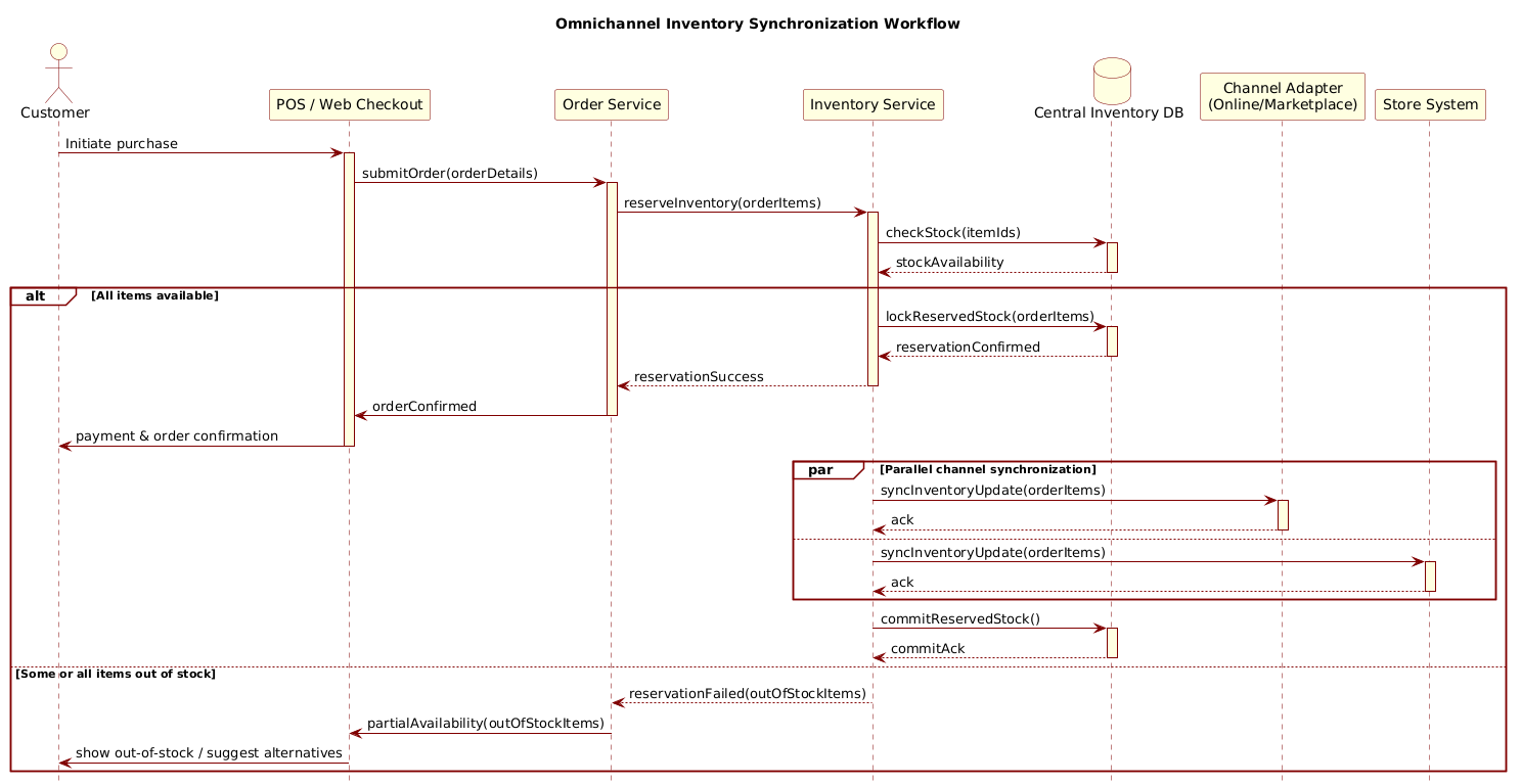
@startuml
!include https://static.visual-paradigm.com/web/resources/plantuml-stdlib/themes/rose.puml

title Omnichannel Inventory Synchronization Workflow

/'
This sequence diagram illustrates the inventory synchronization process
across multiple sales channels (e.g., Online Store, Physical Store, and Marketplace)
within a Retail Management System.

The workflow covers:
- Real-time inventory updates after a sales transaction.
- Validation of stock availability across channels.
- Synchronization with the central inventory database.
- Alternative flows for out-of-stock scenarios and channel-specific updates.
'/

actor "Customer" as Customer
participant "POS / Web Checkout" as Checkout
participant "Order Service" as OrderService
participant "Inventory Service" as InventoryService
database "Central Inventory DB" as CentralDB
participant "Channel Adapter\n(Online/Marketplace)" as ChannelAdapter
participant "Store System" as StoreSystem

Customer -> Checkout: Initiate purchase
activate Checkout

Checkout -> OrderService: submitOrder(orderDetails)
activate OrderService

OrderService -> InventoryService: reserveInventory(orderItems)
activate InventoryService

InventoryService -> CentralDB: checkStock(itemIds)
activate CentralDB
CentralDB --> InventoryService: stockAvailability
deactivate CentralDB

alt All items available
    InventoryService -> CentralDB: lockReservedStock(orderItems)
    activate CentralDB
    CentralDB --> InventoryService: reservationConfirmed
    deactivate CentralDB

    InventoryService --> OrderService: reservationSuccess
    deactivate InventoryService

    OrderService -> Checkout: orderConfirmed
    deactivate OrderService

    Checkout -> Customer: payment & order confirmation
    deactivate Checkout

    par Parallel channel synchronization
        InventoryService -> ChannelAdapter: syncInventoryUpdate(orderItems)
        activate ChannelAdapter
        ChannelAdapter --> InventoryService: ack
        deactivate ChannelAdapter
    else
        InventoryService -> StoreSystem: syncInventoryUpdate(orderItems)
        activate StoreSystem
        StoreSystem --> InventoryService: ack
        deactivate StoreSystem
    end

    InventoryService -> CentralDB: commitReservedStock()
    activate CentralDB
    CentralDB --> InventoryService: commitAck
    deactivate CentralDB

else Some or all items out of stock
    InventoryService --> OrderService: reservationFailed(outOfStockItems)
    deactivate InventoryService

    OrderService -> Checkout: partialAvailability(outOfStockItems)
    deactivate OrderService

    Checkout -> Customer: show out-of-stock / suggest alternatives
    deactivate Checkout
end

@endumlStep-by-Step Architectural Walkthrough
Building this diagram involves four distinct phases: setting the visual theme, defining entities, mapping the primary flow, and handling complex logic branches.
Phase 1: Canvas Configuration & Layout Directives
Before defining any participants, we configure the visual style to ensure the diagram looks professional. VPasCode supports PlantUML standard library themes. We include the rose theme to give the diagram a consistent, modern aesthetic.
!include https://static.visual-paradigm.com/web/resources/plantuml-stdlib/themes/rose.pumlNext, we define the title and add a comment block to document the diagram’s purpose. Comments in PlantUML are wrapped in single forward slashes /' and /'.
title Omnichannel Inventory Synchronization Workflow

/'
This sequence diagram illustrates...
'/
Phase 2: Declaring Core Entities, Actors, and Boundaries
We declare the lifelines that will participate in the interaction. PlantUML supports specific keywords like actor for human users and database for data stores. For services, we use participant.
actor "Customer" as Customer
participant "POS / Web Checkout" as Checkout
database "Central Inventory DB" as CentralDB
Using the as keyword allows us to assign a short alias (e.g., Customer) to a longer label, keeping the diagram clean while retaining descriptive context.
Phase 3: Mapping Data Flows & Key Interactions
The core logic begins with the customer initiating a purchase. We use solid arrows -> for synchronous requests and dashed arrows --> for return messages. Activation bars are explicitly managed using activate and deactivate to control the visual height of the lifelines.
Customer -> Checkout: Initiate purchase
activate Checkout
Checkout -> OrderService: submitOrder(orderDetails)
activate OrderService
This phase establishes the primary call chain: Checkout calls OrderService, which calls InventoryService, which queries the CentralDB.
Phase 4: Grouping, Annotations & Visual Polish
Complex workflows require branching logic. We use the alt block to represent the decision point: Are all items available? Inside the alt block, we can nest parallel processing using par and else clauses.
alt All items available
    ...success flow...
else Some or all items out of stock
    ...failure flow...
end
This structure ensures that the diagram clearly communicates the conditional nature of inventory reservation and error handling.
Syntax & Keyword Deep Dive
Understanding the specific PlantUML syntax is crucial for mastering diagram-as-code. Here is a breakdown of the key features used in this retail workflow model.
actor: Defines a human participant. Used here for theCustomerinitiating the transaction.participant: Represents a software component or service. Used forCheckout,OrderService, andInventoryService.database: Specifically models a data store. Used forCentralDBto distinguish it from application logic.->(Arrow): Indicates a synchronous message or request. The sender waits for a response.-->(Dashed Arrow): Indicates a return message or response. Used for data retrieval or acknowledgments.activate/deactivate: Explicitly controls the activation bar on a lifeline. While often automatic, explicit control ensures precise visual representation of long-running processes.alt/else/end: Creates a conditional fragment. The diagram renders only one path based on the logical condition (e.g., stock availability).par/end: Represents parallel processing. In this model, it shows that channel synchronization happens concurrently with the main flow.title: Sets the main heading of the diagram./' ... '/': Multi-line comment block for documentation.
Best Practices & Pitfalls to Avoid
To maintain high-quality diagrams in VPasCode, follow these architectural modeling guidelines:
- Keep Diagrams Modular: Avoid cramming an entire system into one sequence diagram. Focus on specific workflows like “Inventory Sync” or “Order Placement” separately.
- Consistent Naming: Use the
asalias feature to keep labels short in the diagram but descriptive in the code comments. This reduces visual clutter. - Manage Visual Complexity: Use
altblocks sparingly. If a diagram has too many nested conditions, consider splitting it into multiple diagrams for different scenarios. - Use Themes for Branding: Leverage PlantUML standard themes (like
rose) to ensure diagrams look professional and consistent across your documentation without manual styling.
Start Building PlantUML Sequence Diagrams Faster with VPasCode
Test, preview, and customize your retail inventory workflow diagrams instantly in the browser with VPasCode, the free PlantUML editor.