


In the competitive landscape of modern retail, customer retention is often driven by sophisticated loyalty programs. These systems must seamlessly manage complex interactions between human users (customers and administrators) and backend infrastructure (payment gateways, CRM databases, and notification services). A critical challenge for software architects and business analysts is clearly defining the functional boundaries of these systems before a single line of code is written.

Use Case Diagrams serve as the blueprint for this functional architecture. They provide a high-level visual summary of who interacts with the system and what actions they can perform. However, traditional drag-and-drop diagramming tools often lack the precision and versionability required for complex technical documentation. This is where diagram-as-code shines.
By using PlantUML within the VPasCode editor, architects can define system requirements in plain text, ensuring consistency, clarity, and instant rendering. This tutorial demonstrates how to construct a professional Use Case Diagram for a Loyalty Program Management system, leveraging VPasCode’s browser-based capabilities to visualize the interaction between internal actors and external integrations without any local installation.
Understanding the Model: Purpose, Scope & Problem Framing
Diagram Abstraction & Representation
A Use Case Diagram is not a flowchart; it is a functional model. It answers the question: “What can the system do for the user?” In this specific context, we are modeling the functional requirements of a loyalty platform. The diagram abstracts away implementation details (like database schemas or API endpoints) and focuses purely on the value exchange.
Key elements in this abstraction include:
- Actors: Representations of human roles (Customer, Admin) or external systems (Payment Gateway, CRM) that initiate interactions.
- Use Cases: The specific goals or functions the system provides (e.g., “Redeem Rewards”, “Sync Data”).
- System Boundary: The box that defines the scope of the software being modeled. Anything inside is part of the system; anything outside is external.
Target Domain Scope & Scenario
This diagram focuses specifically on the Retail Industry context. The system boundaries are drawn to encompass the core loyalty logic—managing points, processing transactions, and maintaining member data. Crucially, the diagram distinguishes between Primary Actors (internal users interacting directly with the loyalty system) and Secondary Actors (external systems that support the core functionality).
For example, while a Customer triggers a transaction, the actual monetary processing is delegated to a Payment Gateway. This separation clarifies responsibility boundaries, which is vital for microservices architecture and API contract design.
Key Takeaways & Educational Insights
By following this guide, you will gain the ability to:
- Clearly delineate system scope using PlantUML rectangles.
- Organize actors logically (left-to-right flow for primary vs. secondary).
- Document external dependencies without cluttering the core business logic.
- Utilize VPasCode for instant, live rendering of your architectural decisions.
Complete Diagram & Full Source Code
Before diving into the step-by-step construction, here is the complete, finalized blueprint for the Loyalty Program Management Use Case Diagram. This code defines the system boundary, the eight core use cases, and the connections between internal users and external services.
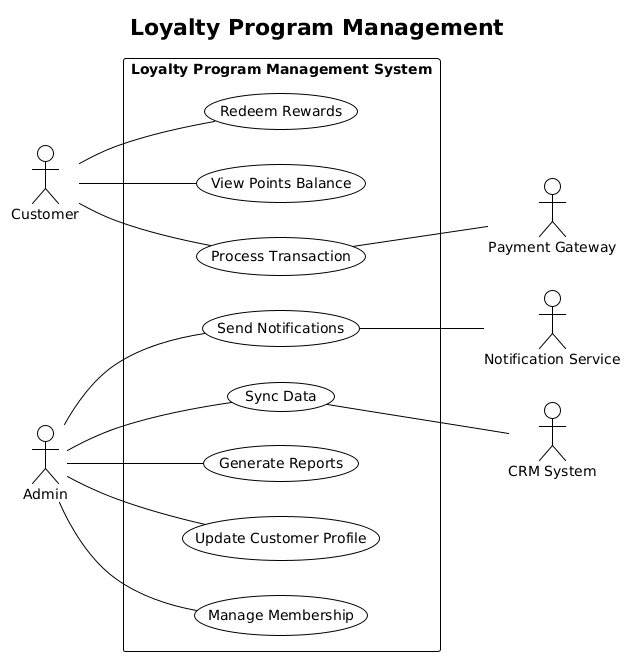
You can view and edit this diagram instantly using the code block below. It is ready to be pasted directly into the VPasCode editor.
@startuml
    !theme plain
    title Loyalty Program Management
    /' This diagram illustrates the functional requirements of a Loyalty Program Management System, defining interactions between internal users (customers and administrators) and external systems to manage member points, rewards, and data synchronization. '/

    left to right direction

    actor Customer
    actor Admin

    rectangle "Loyalty Program Management System" as SystemBoundary {
        usecase "View Points Balance" as UC1
        usecase "Redeem Rewards" as UC2
        usecase "Process Transaction" as UC3
        usecase "Manage Membership" as UC4
        usecase "Update Customer Profile" as UC5
        usecase "Generate Reports" as UC6
        usecase "Send Notifications" as UC7
        usecase "Sync Data" as UC8
    }

    actor "Payment Gateway" as PG
    actor "CRM System" as CRM
    actor "Notification Service" as NS

    Customer -- UC1
    Customer -- UC2
    Customer -- UC3

    Admin -- UC4
    Admin -- UC5
    Admin -- UC6
    Admin -- UC7
    Admin -- UC8

    UC3 -- PG
    UC7 -- NS
    UC8 -- CRM

@endumlStep-by-Step Architectural Walkthrough
Building this diagram is a structured process. We will break it down into four logical phases, moving from global configuration to specific entity definitions and finally to relationship mapping.
Phase 1: Canvas Configuration & Layout Directives
Every PlantUML diagram begins with setup commands that define the rendering engine’s behavior. We start by initializing the diagram and selecting a theme.
First, we declare the start and end of the diagram using @startuml and @enduml. This is mandatory for the parser to recognize the block as a valid diagram.
@startuml
    !theme plain
    title Loyalty Program Management
    /' This diagram illustrates the functional requirements of a Loyalty Program Management System, defining interactions between internal users (customers and administrators) and external systems to manage member points, rewards, and data synchronization. '/

    left to right direction
We apply the !theme plain directive to ensure a clean, minimalist aesthetic suitable for technical documentation. Next, the title command provides a clear header for the diagram. Finally, we add a comment block using /' and '/ to describe the context of the model. This documentation is invisible in the rendered image but crucial for future readers.
We also set the layout direction to left to right direction. This ensures that primary actors appear on the left and secondary actors on the right, creating a natural reading flow for the diagram.
Phase 2: Declaring Core Entities, Actors, and Boundaries
Now we define the participants. In a Use Case diagram, we distinguish between human actors and system boundaries.
    actor Customer
    actor Admin

    rectangle "Loyalty Program Management System" as SystemBoundary {
        usecase "View Points Balance" as UC1
        usecase "Redeem Rewards" as UC2
        usecase "Process Transaction" as UC3
        usecase "Manage Membership" as UC4
        usecase "Update Customer Profile" as UC5
        usecase "Generate Reports" as UC6
        usecase "Send Notifications" as UC7
        usecase "Sync Data" as UC8
    }
We declare the primary actors first: Customer and Admin. Then, we define the system boundary using the rectangle keyword. Inside this rectangle, we list all the use cases. Each use case is assigned a unique identifier (e.g., as UC1) to simplify later referencing. This creates a clear visual box representing the scope of the software.
Phase 3: Mapping Data Flows & Key Interactions
With the actors and use cases defined, we must now connect them to show who does what. We use the double dash -- to represent associations.
    Customer -- UC1
    Customer -- UC2
    Customer -- UC3

    Admin -- UC4
    Admin -- UC5
    Admin -- UC6
    Admin -- UC7
    Admin -- UC8
Notice the pattern: Primary actors (Customer, Admin) are connected to the use cases inside the boundary. We omit arrowheads for these associations as per standard use case notation conventions, implying a bidirectional or simple interaction.
Phase 4: Grouping, Annotations & Visual Polish
The final phase involves defining secondary actors (external systems) and connecting them to the specific use cases they support. This highlights the system’s dependencies.
    actor "Payment Gateway" as PG
    actor "CRM System" as CRM
    actor "Notification Service" as NS

    UC3 -- PG
    UC7 -- NS
    UC8 -- CRM
We define the secondary actors outside the main system boundary. Then, we connect them to the specific use cases that require their services. For instance, Process Transaction (UC3) connects to the Payment Gateway (PG), indicating that the transaction functionality relies on external payment processing.
Syntax & Keyword Deep Dive
To master this diagram, it is essential to understand the specific PlantUML syntax used. Here is a breakdown of the critical keywords:
@startuml/@enduml: These are the delimiters that mark the beginning and end of the diagram definition.!theme plain: A directive that applies the “plain” visual theme, removing gradients and shadows for a clean technical look.title: Adds a bold header text at the top of the diagram./' ... '/: The syntax for multi-line comments. Content here is not rendered visually but is preserved in the source code for documentation.actor: Defines an entity that interacts with the system. Syntax:actor Name.rectangle ... as ...: Creates a boundary box. Theaskeyword assigns an ID to the rectangle for reference.usecase: Defines a functional goal. Syntax:usecase "Label" as ID.--: The association operator. It draws a line between two elements without arrowheads by default.left to right direction: A layout directive that forces the rendering engine to arrange elements horizontally from left to right.
Best Practices & Pitfalls to Avoid
When creating diagrams-as-code, following best practices ensures maintainability and clarity. Here are key recommendations based on this tutorial:
- Consistent Naming Conventions: Always assign IDs to use cases and rectangles (e.g.,
as UC1,as SystemBoundary). This prevents errors when referencing them in association lines later. - Clear Actor Separation: Visually distinguish between primary actors (users) and secondary actors (external systems). In this diagram, placing primary actors on the left and secondary on the right creates a logical flow.
- Scope the Boundary: Be careful not to include external systems inside the
rectangle. The boundary should only contain the system you are modeling. External dependencies should remain outside. - Use Comments for Context: Never skip the comment block
/' ... '/. It provides immediate context for anyone reading the code without needing to guess the diagram’s purpose.
Try It Yourself with VPasCode
Start Building Use Case Diagrams Faster with VPasCode
Instantly visualize your system requirements and functional models in your browser with VPasCode, the free PlantUML editor. No installation required.