


In the realm of financial technology, clarity is currency. When designing systems like Automated Teller Machines (ATMs), the complexity of interactions between hardware, software, and banking backends must be meticulously documented. A sequence diagram serves as the definitive blueprint for these temporal interactions, ensuring that developers and stakeholders understand the precise order of messages, data flows, and error handling mechanisms.

However, traditional diagramming tools often require heavy installations, manual drawing, or complex licensing. This is where VPasCode transforms the workflow. As a free, web-based diagram-as-code tool, VPasCode allows software architects to define system interactions using text-based PlantUML syntax. This approach enhances architectural clarity, enables rapid visual prototyping, and keeps technical documentation living and versionable without the friction of GUI drag-and-drop.
In this masterclass, we will construct a professional-grade sequence diagram modeling a cash withdrawal scenario. By leveraging VPasCode, you will see how to instantly render, validate, and refine complex logic flows directly in your browser.
Understanding the Model: Purpose, Scope & Problem Framing
Before writing a single line of code, it is essential to understand the modeling abstraction and the domain scenario we are addressing.
Diagram Abstraction & Representation
A sequence diagram is a time-based interaction diagram. It models how objects or participants communicate with one another over time. In the context of PlantUML and VPasCode, this abstraction is critical for financial systems because:
- Lifelines: Represent the system boundaries (e.g., Customer, ATM Machine, Account Service).
- Messages: Capture synchronous and asynchronous calls (e.g., “Insert Card”, “Validate PIN”).
- Activation Bars: Indicate when a participant is actively processing a request, highlighting concurrency and processing bottlenecks.
Target Domain Scope & Scenario
This diagram focuses specifically on the Cash Withdrawal workflow within an ATM ecosystem. The scope includes:
- Authentication: Card insertion and PIN validation.
- Transaction Logic: Balance checks and fund debiting.
- Physical Interaction: Cash dispensing and card return.
- Error Handling: Alternative flows for invalid PINs or insufficient funds.
Key Takeaways & Educational Insights
By building this model, you will gain insights into:
- How to structure alt blocks to manage conditional logic cleanly.
- Best practices for naming participants to reflect physical vs. logical services.
- How to use VPasCode to visualize the flow of control without writing Java or C# code.
Complete Diagram & Full Source Code
Below is the complete, ready-to-use source code for the ATM Withdrawal Sequence Diagram. This code includes the VPasCode theme inclusion, actor definitions, and the full logic flow including error handling.
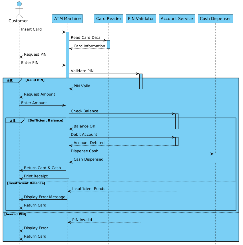
@startuml
!include https://static.visual-paradigm.com/web/resources/plantuml-stdlib/themes/vp.puml

actor Customer
participant "ATM Machine" as ATM
participant "Card Reader" as CardReader
participant "PIN Validator" as PINValidator
participant "Account Service" as AccountService
participant "Cash Dispenser" as CashDispenser

Customer -> ATM: Insert Card
activate ATM
ATM -> CardReader: Read Card Data
activate CardReader
CardReader --> ATM: Card Information
deactivate CardReader

ATM -> Customer: Request PIN
Customer -> ATM: Enter PIN
ATM -> PINValidator: Validate PIN
activate PINValidator

alt Valid PIN
    PINValidator --> ATM: PIN Valid
    deactivate PINValidator

    ATM -> Customer: Request Amount
    Customer -> ATM: Enter Amount
    ATM -> AccountService: Check Balance
    activate AccountService

    alt Sufficient Balance
        AccountService --> ATM: Balance OK
        deactivate AccountService

        ATM -> AccountService: Debit Account
        activate AccountService
        AccountService --> ATM: Account Debited
        deactivate AccountService

        ATM -> CashDispenser: Dispense Cash
        activate CashDispenser
        CashDispenser --> ATM: Cash Dispensed
        deactivate CashDispenser

        ATM -> Customer: Return Card & Cash
        ATM -> Customer: Print Receipt
        deactivate ATM
    else Insufficient Balance
        AccountService --> ATM: Insufficient Funds
        deactivate AccountService
        ATM -> Customer: Display Error Message
        ATM -> Customer: Return Card
        deactivate ATM
    end
else Invalid PIN
    PINValidator --> ATM: PIN Invalid
    deactivate PINValidator
    ATM -> Customer: Display Error
    ATM -> Customer: Return Card
    deactivate ATM
end
@endumlStep-by-Step Architectural Walkthrough
Let’s break down the construction of this diagram into four distinct phases. This walkthrough demonstrates how to translate business requirements into PlantUML syntax using VPasCode.
Phase 1: Canvas Configuration & Layout Directives
Every PlantUML diagram requires a start command and optional configuration. In this scenario, we utilize the VPasCode theme to ensure the diagram matches the standard Visual Paradigm aesthetic.
We begin with the @startuml directive, which signals the renderer to begin parsing the diagram code. Immediately following this, we include the external theme library. This ensures consistent styling for actors and participants without manually defining skin parameters.
@startuml
!include https://static.visual-paradigm.com/web/resources/plantuml-stdlib/themes/vp.puml
Phase 2: Declaring Core Entities, Actors, and Boundaries
Next, we define the participants. In sequence diagrams, it is crucial to distinguish between human actors and system components.
- Actor: The
Customerrepresents the human user initiating the request. - Participants: The
ATM Machineacts as the orchestrator. Components likeCardReader,PINValidator, andAccountServicerepresent specific functional modules.
actor Customer
participant "ATM Machine" as ATM
participant "Card Reader" as CardReader
participant "PIN Validator" as PINValidator
participant "Account Service" as AccountService
participant "Cash Dispenser" as CashDispenser
Phase 3: Mapping Data Flows & Key Interactions
This phase maps the chronological flow of messages. We use the -> arrow for synchronous requests and --> for return messages. Activation bars are added using activate and deactivate to show processing duration.
For example, the card reading process involves the ATM activating the Card Reader, retrieving data, and then deactivating it.
Customer -> ATM: Insert Card
activate ATM
ATM -> CardReader: Read Card Data
activate CardReader
CardReader --> ATM: Card Information
deactivate CardReader
Phase 4: Grouping, Annotations & Visual Polish
Complex workflows require conditional logic. We use the alt keyword to create combined fragments. This groups alternative flows, such as “Valid PIN” vs. “Invalid PIN”, or “Sufficient Balance” vs. “Insufficient Balance”.
Each alt block must be closed with an end statement. This structure keeps the diagram readable by visually separating error paths from the happy path.
alt Valid PIN
    PINValidator --> ATM: PIN Valid
    deactivate PINValidator

    ATM -> Customer: Request Amount
    ...
else Insufficient Balance
    ...
end
Syntax & Keyword Deep Dive
To fully leverage VPasCode and PlantUML, you must understand the specific syntax features used in this diagram.
actor: Defines a human or external system that initiates the interaction. In this case, theCustomer.participant: Defines a system component, service, or device. We assign aliases (e.g.,as ATM) to keep message references concise.->(Solid Arrow): Represents a synchronous message call where the sender waits for a response.-->(Dashed Arrow): Represents an asynchronous message or a return response.activate/deactivate: Controls the vertical activation bar on a lifeline, indicating the period during which the participant is busy processing a request.alt/else/end: These keywords create a combined fragment box.altdefines the alternative path,elsedefines the fallback condition, andendcloses the block.
Best Practices & Pitfalls to Avoid
When creating sequence diagrams with PlantUML, adhering to best practices ensures your diagrams remain maintainable and readable.
- Keep Diagrams Modular: If a workflow becomes too complex, consider splitting it into multiple diagrams (e.g., one for Authentication, one for Withdrawal). Avoid cramming unrelated flows into a single sequence.
- Use Descriptive Aliases: Always use the
askeyword to assign short aliases to long participant names. This makes the message lines cleaner (e.g.,ATMinstead ofATM Machine). - Manage Visual Complexity: Use
altblocks to group logic rather than nesting multiple layers of arrows. Ensure everyaltblock has a correspondingend. - Consistent Naming Conventions: Use Title Case for participant names to distinguish them from message text. This visual distinction helps readers parse the diagram faster.
Start Building Sequence Diagrams Faster with VPasCode
Master complex financial workflows like ATM withdrawals with instant browser-based rendering in VPasCode, our free PlantUML editor.