


In the modern financial technology landscape, trust and transparency are the cornerstones of any escrow service. Whether facilitating a real estate transaction, handling freelance payments, or securing high-value asset transfers, the mechanism for releasing funds must be robust, auditable, and logically sound. Visualizing these workflows is not merely a documentation exercise; it is a critical engineering task that prevents financial discrepancies and ensures compliance with security protocols.

Activity diagrams offer the ideal abstraction for mapping these complex business processes. By utilizing diagram-as-code with PlantUML within VPasCode, architects can rapidly prototype, validate, and document the lifecycle of a fund release. This approach eliminates the friction of manual drawing tools, allowing developers to focus on the logic of the transaction flow rather than the aesthetics of the diagram. The result is a living document that accurately reflects the system’s behavior, from the initial buyer confirmation to the final seller notification.
Understanding the Model: Purpose, Scope & Problem Framing
Diagram Abstraction & Representation
An Activity Diagram is the standard UML notation for modeling the flow of control and data between activities. In the context of an Escrow Service System, this diagram serves as a blueprint for the backend orchestration logic. It visualizes the state transitions of a transaction as it moves through various stages of verification and settlement. The swimlane structure is particularly vital here, as it segregates responsibilities between the Buyer, the System, and the Seller, clarifying who initiates an action and who executes it.
Target Domain Scope & Scenario
This tutorial focuses specifically on the Fund Release Process. The scope is bounded by the moment the buyer confirms receipt of goods to the final notification of fund transfer completion. It intentionally excludes the initial deposit phase, focusing instead on the conditional logic required to authorize the release. This includes validating the escrow balance, managing parallel notifications to stakeholders, and handling error states where funds are insufficient.
Key Takeaways & Educational Insights
By building this model, you will gain clarity on:
- Separation of Concerns: How to logically group actions by actor using swimlanes.
- Conditional Logic: Implementing decision points (if/else) to handle insufficient balance scenarios.
- Parallel Processing: Utilizing fork/join constructs to model simultaneous notifications to buyers and sellers.
Complete Diagram & Full Source Code
Below is the finalized blueprint for the Escrow Fund Release Process. This diagram demonstrates how to structure a professional-grade activity diagram using swimlanes, conditional branching, and parallel execution paths.
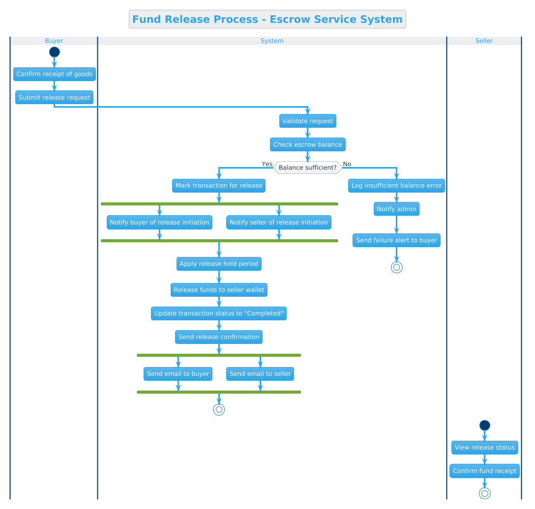
Copy the complete code below to render the diagram in VPasCode:
@startuml
!theme cerulean
title Fund Release Process - Escrow Service System

|Buyer|
|System|
|Seller|

|Buyer|
start
:Confirm receipt of goods;
:Submit release request;

|System|
:Validate request;
:Check escrow balance;

if (Balance sufficient?) then (Yes)
  :Mark transaction for release;
  fork
    :Notify buyer of release initiation;
  fork again
    :Notify seller of release initiation;
  end fork
  :Apply release hold period;
  :Release funds to seller wallet;
  :Update transaction status to "Completed";
  :Send release confirmation;
  fork
    :Send email to buyer;
  fork again
    :Send email to seller;
  end fork
  stop
else (No)
  :Log insufficient balance error;
  :Notify admin;
  :Send failure alert to buyer;
  stop
endif

|Seller|
start
:View release status;
:Confirm fund receipt;
stop

@endumlStep-by-Step Architectural Walkthrough
Building this diagram in VPasCode involves four distinct phases: setting the visual theme, defining the organizational structure, implementing the logic flow, and refining the termination points.
Phase 1: Canvas Configuration & Layout Directives
Before defining the actors, we establish the visual context. We begin by setting the theme to cerulean, which provides a clean, professional color palette suitable for financial documentation. We also add a descriptive title to the canvas.
@startuml
!theme cerulean
title Fund Release Process - Escrow Service System
This setup ensures that when the diagram renders, it immediately communicates the domain context (Escrow) and the specific process (Fund Release) without ambiguity.
Phase 2: Declaring Core Entities, Actors, and Boundaries
The core of this diagram is the swimlane structure. Swimlanes allow us to map specific responsibilities to specific roles. We define three lanes: |Buyer|, |System|, and |Seller|. This ensures that every action is attributed to the correct entity.
|Buyer|
|System|
|Seller|
By grouping these at the top of the diagram, we create a clear visual boundary. The |Buyer| lane will handle initiation, |System| will handle validation and execution, and |Seller| will handle receipt confirmation.
Phase 3: Mapping Data Flows & Key Interactions
With the lanes defined, we map the chronological flow. We start the process in the |Buyer| lane with the initial actions, then transition to the |System| lane for validation.
|Buyer|
start
:Confirm receipt of goods;
:Submit release request;

|System|
:Validate request;
:Check escrow balance;
Here, we introduce the critical decision point using the if statement. This checks if the escrow balance is sufficient. If the balance is sufficient, the flow enters a fork block to handle parallel notifications, demonstrating the system’s ability to manage concurrent tasks.
if (Balance sufficient?) then (Yes)
  :Mark transaction for release;
  fork
    :Notify buyer of release initiation;
  fork again
    :Notify seller of release initiation;
  end fork
The fork and fork again syntax allows multiple activities to run simultaneously, which is common in financial systems where multiple stakeholders must be informed at the same time.
Phase 4: Grouping, Annotations & Visual Polish
Finally, we ensure the diagram terminates correctly. Both the success path (after notifications) and the failure path (insufficient balance) must lead to a stop node. This prevents the diagram from implying an infinite loop or an unresolved state.
  stop
else (No)
  :Log insufficient balance error;
  :Notify admin;
  :Send failure alert to buyer;
  stop
endif
We also include a separate start and stop sequence for the |Seller| lane to show their perspective on the process, ensuring the diagram is comprehensive across all user roles.
Syntax & Keyword Deep Dive
To master this diagram, you must understand the specific PlantUML syntax features used to construct the logic.
@startuml/@enduml: The mandatory wrapper tags that define the beginning and end of a PlantUML diagram block.|Lane|: Defines a swimlane. Text following this tag belongs to that specific actor until a new lane tag is declared.start/stop: Defines the entry and exit points of the activity flow.if (Condition) then (Result): Creates a decision diamond. The flow splits based on whether the condition inside the parentheses is true or false.fork/fork again/end fork: Creates parallel processing paths. All activities betweenforkandend forkoccur concurrently.!theme cerulean: A directive to apply a specific visual theme to the rendered diagram.
Best Practices & Pitfalls to Avoid
When creating activity diagrams for financial systems, adhere to these modeling guidelines to ensure clarity and maintainability.
- Limit Swimlane Depth: Do not create too many swimlanes. If you find yourself adding more than 3-4 lanes, consider grouping related actors or splitting the diagram into sub-processes.
- Consistent Labeling: Use imperative verbs for activity labels (e.g., “Validate request” instead of “Validation of request”). This makes the diagram read like a set of instructions.
- Handle Error Paths Explicitly: Never assume success. Always define what happens when a condition fails (e.g., the
elsebranch in the balance check). In finance, error logging and notification are as important as the success path. - Test with VPasCode: Use the live editor to validate your logic. Syntax errors in PlantUML can cause rendering failures, so incremental testing is key.
Start Building PlantUML Activity Diagrams Faster with VPasCode
Create professional finance workflow diagrams instantly in your browser with VPasCode, the free PlantUML editor for architects and developers.