


In the rapidly evolving landscape of healthcare technology, clarity in process modeling is not just a convenience—it is a critical operational requirement. Whether designing a new pharmacy management system or auditing existing workflows, visualizing the lifecycle of a prescription is essential for ensuring patient safety, regulatory compliance, and operational efficiency. Traditional hand-drawn diagrams often lack precision and become outdated quickly, creating a disconnect between documentation and reality.

This tutorial demonstrates how to leverage PlantUML, a powerful diagram-as-code tool, to build a professional-grade Activity Diagram for a Pharmacy Prescription Fulfillment Process. By using VPasCode, the free web-based editor, architects and developers can define complex workflows in text, render them instantly, and maintain living documentation that evolves with the system. This approach eliminates the friction of manual drawing tools, allowing teams to focus on logic, boundaries, and interaction flows rather than pixel-perfect alignment.
We will explore a scenario involving multiple actors—Customers, the Pharmacy System, Pharmacists, and Pharmacy Staff—interacting through various conditional and parallel paths. This level of detail is crucial for identifying bottlenecks, such as insurance verification delays, before a single line of production code is written.
Understanding the Model: Purpose, Scope & Problem Framing
Before diving into the syntax, it is vital to understand the abstraction we are modeling. An Activity Diagram is the ideal notation for representing the dynamic behavior of a system, specifically focusing on the flow of control from one activity to another.
Diagram Abstraction & Representation
In this context, the Activity Diagram serves as a blueprint for the business logic governing prescription fulfillment. It maps the journey of a request from initiation (submission) to completion (fulfillment). The use of swimlanes is a critical architectural decision here; they partition the diagram by responsibility. This visual separation clarifies which actor is accountable for each step, preventing ambiguity in role definitions. For instance, the Pharmacist lane handles clinical verification, while the Pharmacy System lane handles data validation and inventory updates.
Target Domain Scope & Scenario
The scope of this diagram covers the core fulfillment loop. It intentionally excludes peripheral processes like marketing or billing disputes to maintain focus on the critical path. The scenario begins when a customer submits a prescription via an app or in-person and ends when the inventory is updated and the fulfillment is recorded. This boundary ensures the diagram remains readable while capturing the high-stakes interactions that require system validation.
Key Takeaways & Educational Insights
By constructing this model, readers will gain insights into:
- Role Segmentation: How to effectively use swimlanes to assign system vs. human responsibilities.
- Control Flow: Managing complex logic such as insurance checks (conditional) and parallel processing (fork/join).
- Error Handling: Visualizing failure paths (e.g., invalid prescriptions) and how they terminate the process gracefully.
Complete Diagram & Full Source Code
Below is the finalized blueprint for the Prescription Fulfillment Process. This diagram utilizes the aws-orange theme for a professional, modern aesthetic and integrates multiple swimlanes to represent the ecosystem.
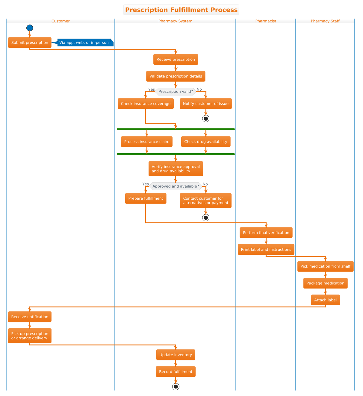
The following code block contains the complete source code. You can copy this entire block into the VPasCode editor to render the diagram instantly.
@startuml
!theme aws-orange
title Prescription Fulfillment Process

|Customer|
start
:Submit prescription;
note right: Via app, web, or in-person

|Pharmacy System|
:Receive prescription;
:Validate prescription details;
if (Prescription valid?) then (Yes)
  :Check insurance coverage;
else (No)
  :Notify customer of issue;
  stop
endif

|Pharmacy System|
fork
  :Process insurance claim;
fork again
  :Check drug availability;
end fork

|Pharmacy System|
:Verify insurance approval
and drug availability;

if (Approved and available?) then (Yes)
  :Prepare fulfillment;
else (No)
  :Contact customer for
alternatives or payment;
  stop
endif

|Pharmacist|
:Perform final verification;
:Print label and instructions;

|Pharmacy Staff|
:Pick medication from shelf;
:Package medication;
:Attach label;

|Customer|
:Receive notification;
:Pick up prescription
or arrange delivery;

|Pharmacy System|
:Update inventory;
:Record fulfillment;
stop
@endumlStep-by-Step Architectural Walkthrough
Building this diagram in VPasCode is a structured process. We will break down the construction into four logical phases, ensuring each architectural component is implemented correctly.
Phase 1: Canvas Configuration & Layout Directives
The first step in any PlantUML project is setting the global style and context. This establishes the visual identity and the title of the diagram. In our code, we begin with the theme directive and the title.
!theme aws-orange
title Prescription Fulfillment Process
The !theme directive applies a predefined color palette (in this case, the AWS orange theme) to the entire diagram, ensuring consistency. The title directive provides a clear heading that appears above the diagram, essential for documentation.
Phase 2: Declaring Core Entities, Actors, and Boundaries
Next, we define the swimlanes. In PlantUML activity diagrams, swimlanes are declared using the pipe character | followed by the lane name. This creates vertical columns that group related activities.
|Customer|
|Pharmacy System|
|Pharmacist|
|Pharmacy Staff|
We define these lanes in the order of the workflow. The Customer lane initiates the process, while the Pharmacy System acts as the central processing hub. The Pharmacist and Pharmacy Staff lanes represent the physical execution of the order. This structure immediately communicates the division of labor.
Phase 3: Mapping Data Flows & Key Interactions
With the lanes established, we populate them with activities. We start the flow in the Customer lane using the start node and proceed to the Pharmacy System lane for validation.
start
:Submit prescription;
:Receive prescription;
:Validate prescription details;
Here, we introduce conditional logic using the if statement. This is critical for handling invalid prescriptions. If the validation fails, the flow moves to the else branch, notifies the customer, and terminates with stop.
if (Prescription valid?) then (Yes)
  :Check insurance coverage;
else (No)
  :Notify customer of issue;
  stop
endif
Phase 4: Grouping, Annotations & Visual Polish
To model real-world complexity, we often need parallel processing. In this scenario, checking insurance and verifying drug availability can happen simultaneously. We use the fork and end fork constructs to represent this concurrency.
fork
  :Process insurance claim;
fork again
  :Check drug availability;
end fork
After the fork, the flow merges automatically. We then add annotations, such as notes, to provide context without cluttering the logic. For example, specifying that prescriptions can be submitted “Via app, web, or in-person” helps clarify input methods.
note right: Via app, web, or in-personSyntax & Keyword Deep Dive
To fully master this diagram, it is important to understand the specific PlantUML keywords used. These syntax elements control the flow and structure of the diagram.
|Lane Name|: Defines a swimlane. Activities following this tag belong to that specific role or system component until a new lane is declared.start/stop: Mark the entry and exit points of the activity flow. A diagram must have exactly onestartnode.if (condition) then (Yes): Creates a decision point. The flow splits based on the boolean result of the condition in parentheses.fork/fork again/end fork: Initiates parallel processing.forksplits the flow into multiple branches, andend forkmerges them back into a single flow.note right: Adds a text annotation attached to the preceding activity, useful for adding context without changing the flow.
Best Practices & Pitfalls to Avoid
When modeling healthcare workflows in PlantUML, adherence to best practices ensures the diagram remains maintainable and readable.
- Maintain Swimlane Clarity: Do not overlap responsibilities between lanes. If an activity requires input from two roles, ensure the arrow crosses the boundary clearly rather than duplicating the node in both lanes.
- Limit Branch Depth: While PlantUML supports deep nesting, excessive
if/elsechains can make the diagram unreadable. Consider simplifying complex conditions into separate sub-activities or usingnoteannotations for secondary logic. - Consistent Naming: Use imperative verbs for activities (e.g., “Validate prescription” rather than “Validation”). This aligns with standard activity diagram conventions and improves readability.
- Test Edge Cases: Always model the “No” path in your conditional logic. In healthcare, failure states (like an invalid prescription) are just as important as success states for system design.
Start Building PlantUML Activity Diagrams Faster with VPasCode
Test, preview, and customize this pharmacy workflow diagram instantly in your browser with VPasCode, the free PlantUML editor for software architects.