


Reverse logistics is often the most complex segment of supply chain management. Unlike forward logistics, where goods flow predictably from manufacturer to consumer, returns involve unpredictable variables, condition assessments, and financial reconciliations. For logistics architects and operations managers, visualizing these flows is critical to identifying bottlenecks and ensuring customer satisfaction. However, traditional diagramming tools often require manual drag-and-drop interactions that can become tedious when modeling complex conditional logic or parallel processes.
Diagram-as-code tools like VPasCode offer a modern alternative. By writing PlantUML code, you can define the structure of your RMA process programmatically. This approach ensures consistency, allows for rapid iteration, and integrates seamlessly into technical documentation. In this masterclass, we will build a professional Activity Diagram for Return Merchandise Authorization (RMA) processing, utilizing swimlanes to clarify responsibilities across Customer, Service, Warehouse, and Finance teams.
Understanding the Model: Purpose, Scope & Problem Framing
Before diving into the syntax, it is essential to understand the architectural abstraction we are building. An Activity Diagram in PlantUML is designed to model the dynamic behavior of a system, focusing on the flow of control and data. In the context of Reverse Logistics, this diagram serves as a blueprint for the Return Merchandise Authorization (RMA) workflow.
Diagram Abstraction & Representation
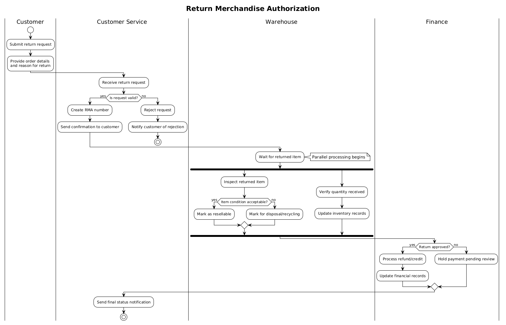
Activity diagrams are ideal for this scenario because they capture the sequence of operations and the decision points that dictate the path of a return request. We use swimlanes to partition the diagram horizontally, assigning specific actions to distinct organizational roles. This visual separation clarifies accountability: the Customer initiates the process, Customer Service validates it, the Warehouse handles the physical goods, and Finance manages the monetary outcome.
Target Domain Scope & Scenario
This model focuses strictly on the post-purchase return lifecycle. It intentionally excludes the initial purchase order or shipping logistics to maintain clarity on the return path. The boundaries include the moment a customer submits a request until the final financial reconciliation or rejection notification is sent. This scope allows us to model critical branching logic, such as validating request data and inspecting item conditions.
Key Takeaways & Educational Insights
By constructing this diagram, you will gain insights into how to manage concurrent processes. Specifically, you will learn how to model parallel flows using the fork keyword, where the warehouse inspects the item while simultaneously verifying inventory quantities. You will also understand how to handle rejection paths gracefully, ensuring that invalid requests do not consume warehouse resources.
Complete Diagram & Full Source Code
Below is the finished blueprint for the Return Merchandise Authorization process. This diagram demonstrates a clean, professional layout using the !theme plain directive for a minimalist aesthetic suitable for technical documentation.
@startuml
!theme plain
title Return Merchandise Authorization

|Customer|
start
:Submit return request;
:Provide order details\nand reason for return;

|Customer Service|
:Receive return request;
if (Is request valid?) then (yes)
  :Create RMA number;
  :Send confirmation to customer;
else (no)
  :Reject request;
  :Notify customer of rejection;
  stop
endif

|Warehouse|
:Wait for returned item;
note right: Parallel processing begins
fork
  :Inspect returned item;
  if (Item condition acceptable?) then (yes)
    :Mark as resellable;
  else (no)
    :Mark for disposal/recycling;
  endif
fork again
  :Verify quantity received;
  :Update inventory records;
end fork

|Finance|
if (Return approved?) then (yes)
  :Process refund/credit;
  :Update financial records;
else (no)
  :Hold payment pending review;
endif

|Customer Service|
:Send final status notification;
stop

@endumlStep-by-Step Architectural Walkthrough
Building this diagram in VPasCode requires a logical sequence of steps. We will break down the construction into four distinct phases, starting with the canvas setup and moving toward complex logic flows.
Phase 1: Canvas Configuration & Layout Directives
Every PlantUML diagram begins with configuration directives that set the global behavior and appearance. We start by defining the diagram type implicitly through the activity keywords, but we explicitly set the visual theme to ensure consistency.
!theme plain
title Return Merchandise Authorization
The !theme plain directive removes decorative backgrounds, creating a clean slate that is ideal for technical manuals. The title directive adds a clear header to the rendered output, ensuring the diagram is self-documenting when exported.
Phase 2: Declaring Core Entities, Actors, and Boundaries
The next step is defining the swimlanes. Swimlanes in PlantUML are declared using the pipe character | followed by the role name. This creates a horizontal band for that actor to operate within.
|Customer|
start
:Submit return request;
We begin with the start node, which is the mandatory entry point for any activity diagram. The colon : prefix denotes an activity action. By assigning the first action to the |Customer| lane, we immediately establish the user’s role in the workflow.
Phase 3: Mapping Data Flows & Key Interactions
Once the lanes are set, we map the logic. This involves decision points (diamonds) and parallel processing. The most complex part of this diagram is the warehouse section, where two tasks happen simultaneously.
fork
  :Inspect returned item;
  ...
fork again
  :Verify quantity received;
  ...
end fork
The fork keyword initiates a parallel branch. fork again adds a second concurrent path. end fork merges these paths back into a single flow. This accurately reflects real-world logistics where inspection and inventory updates occur independently but must both complete before the next stage.
Phase 4: Grouping, Annotations & Visual Polish
To add clarity, we use notes to explain specific states. We also ensure every path terminates. The stop node marks the end of the process, whether it is a successful refund or a rejected request.
note right: Parallel processing begins
...
stop
Adding a note to the right of the fork clarifies the intent of the parallel flow for readers who may not be familiar with the logic. Ending with stop ensures the diagram is syntactically complete and logically sound.
Syntax & Keyword Deep Dive
Understanding the specific PlantUML keywords used in this diagram empowers you to extend the model for future scenarios. Here is a breakdown of the critical syntax elements:
|Role|: Defines a swimlane. The content following this tag until the next|Role|or@endumlbelongs to that actor.start&stop: The mandatory lifecycle markers.startis the green circle entry point, andstopis the red circle termination point.if (condition) then (yes): Creates a decision diamond. The label inside the parentheses defines the condition, andthen/elsedefine the outgoing arrows.fork&end fork: Creates a parallel execution path. This is essential for modeling concurrency, such as processing data while waiting for physical goods.note right: Adds an annotation to the right of the preceding element, useful for adding context without cluttering the flow lines.
Best Practices & Pitfalls to Avoid
When creating activity diagrams for logistics and enterprise systems, adhering to modeling standards ensures the diagram remains maintainable.
- Limit Swimlane Depth: While you can have many lanes, try to keep them to 4-5 maximum. If you have more roles, consider grouping them into broader categories (e.g., “External Stakeholders” vs. “Internal Operations”).
- Balance Forks: Ensure every
forkhas a correspondingend fork. Unmatched forks can cause rendering errors or logical deadlocks in the diagram interpretation. - Clear Decision Labels: Always label the
ifbranches clearly (e.g.,yes/no,approved/rejected). Ambiguous labels make the diagram difficult to audit. - Modularize Complex Flows: If a diagram becomes too long, consider splitting it into sub-activities. For example, the “Warehouse Inspection” could be its own diagram referenced by the main RMA flow.
Try It Yourself with VPasCode
Start Building PlantUML Activity Diagrams Faster with VPasCode
Visualize complex logistics workflows instantly in your browser with VPasCode, our free PlantUML editor for zero-setup live rendering.