


In the rapidly evolving landscape of modern retail, the efficiency of a warehouse often dictates the success of an entire supply chain. As automation technologies like robotic arms, conveyor systems, and intelligent inventory management become standard, the software controlling these physical assets grows increasingly complex. Software architects and engineers face a critical challenge: how to clearly model the static structure of this hybrid system where software logic directly commands physical hardware without ambiguity. Visual modeling bridges this gap, transforming abstract requirements into a concrete blueprint that developers and stakeholders can understand.
Diagramming-as-code offers a superior alternative to drag-and-drop tools for these complex architectures. By writing code to define classes, relationships, and attributes, teams ensure that their documentation remains versioned, reproducible, and easily updated alongside the actual software codebase. PlantUML, a powerful notation for modeling system structures, allows developers to describe class relationships, cardinalities, and system boundaries textually. When combined with a browser-based editor like VPasCode, the process becomes instantaneous, eliminating the need for local environment setup while providing real-time rendering of the architectural vision.

This tutorial guides you through designing a comprehensive Class Diagram for a Warehouse Fulfillment Automation System. We will explore how to model the interaction between the central management software, inventory logic, and automated hardware components. By the end of this guide, you will understand how to leverage PlantUML syntax to define generalization, aggregation, and association relationships, ensuring your system architecture is documented with precision and clarity.
Understanding the Model: Purpose, Scope & Problem Framing
Diagram Abstraction & Representation
A Class Diagram is the foundational blueprint for object-oriented design. In the context of a Warehouse Fulfillment Automation System, this diagram does not model the dynamic flow of events (like a Sequence Diagram) but rather the static structure of the system. It defines the “nouns” of the system: what objects exist (e.g., RoboticArm, Order, InventoryManager) and how they are related. This abstraction is critical for ensuring that the software layers controlling the warehouse hardware are logically sound before implementation begins.
Target Domain Scope & Scenario
The scope of this model covers the core operational loop of a modern automated warehouse. It includes the software control layer (WarehouseManagementSystem, ControlUnit), the data entities representing business transactions (Order, Product), and the physical interface layer (RoboticArm, ConveyorBelt, Sensor). The diagram intentionally excludes peripheral systems like external payment gateways or customer-facing mobile apps to focus on the internal logistics and fulfillment logic.
Key Takeaways & Educational Insights
By constructing this model, you will gain insights into managing multiplicity in relationships (e.g., one Warehouse manages many Orders), distinguishing between ownership (Composition) and usage (Association), and organizing code into logical packages. This clarity prevents architectural drift and ensures that the final codebase accurately reflects the intended system design.
Complete Diagram & Full Source Code
Before diving into the construction steps, review the complete visual output below. This diagram represents the finalized structure of the Warehouse Fulfillment Automation System, showcasing the relationships between software entities and hardware controllers.
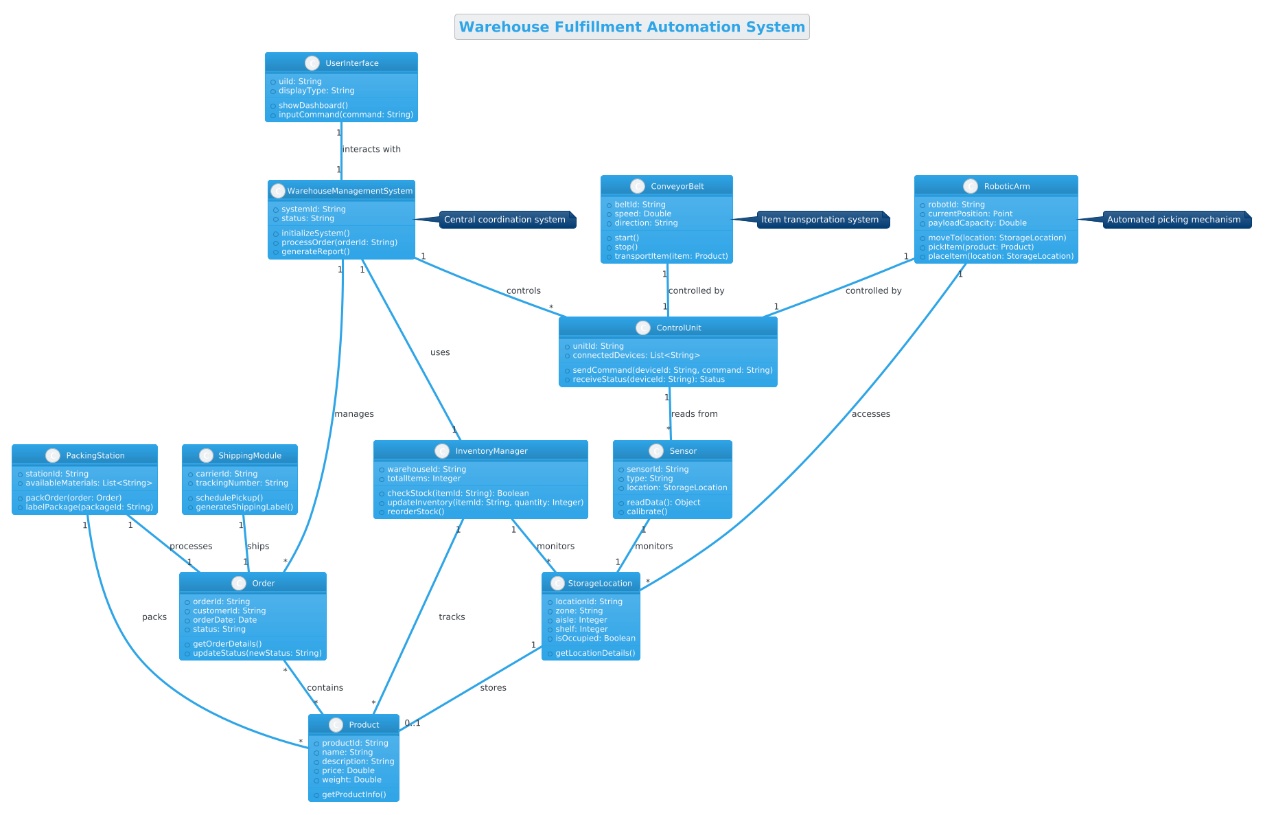
Copy the complete source code below to use in your own projects. This code block is formatted to be directly compatible with the VPasCode interactive editor.
@startuml
!theme cerulean

title Warehouse Fulfillment Automation System

/'
This class diagram models a Warehouse Fulfillment Automation System. It illustrates the core components involved in automated order processing, inventory management, and robotic fulfillment within a modern warehouse environment. The system integrates software control layers with physical hardware components to streamline the picking, packing, and shipping processes.
'/

class WarehouseManagementSystem {
    +systemId: String
    +status: String
    +initializeSystem()
    +processOrder(orderId: String)
    +generateReport()
}

class Order {
    +orderId: String
    +customerId: String
    +orderDate: Date
    +status: String
    +getOrderDetails()
    +updateStatus(newStatus: String)
}

class InventoryManager {
    +warehouseId: String
    +totalItems: Integer
    +checkStock(itemId: String): Boolean
    +updateInventory(itemId: String, quantity: Integer)
    +reorderStock()
}

class Product {
    +productId: String
    +name: String
    +description: String
    +price: Double
    +weight: Double
    +getProductInfo()
}

class StorageLocation {
    +locationId: String
    +zone: String
    +aisle: Integer
    +shelf: Integer
    +isOccupied: Boolean
    +getLocationDetails()
}

class RoboticArm {
    +robotId: String
    +currentPosition: Point
    +payloadCapacity: Double
    +moveTo(location: StorageLocation)
    +pickItem(product: Product)
    +placeItem(location: StorageLocation)
}

class ConveyorBelt {
    +beltId: String
    +speed: Double
    +direction: String
    +start()
    +stop()
    +transportItem(item: Product)
}

class PackingStation {
    +stationId: String
    +availableMaterials: List<String>
    +packOrder(order: Order)
    +labelPackage(packageId: String)
}

class ShippingModule {
    +carrierId: String
    +trackingNumber: String
    +schedulePickup()
    +generateShippingLabel()
}

class Sensor {
    +sensorId: String
    +type: String
    +location: StorageLocation
    +readData(): Object
    +calibrate()
}

class ControlUnit {
    +unitId: String
    +connectedDevices: List<String>
    +sendCommand(deviceId: String, command: String)
    +receiveStatus(deviceId: String): Status
}

class UserInterface {
    +uiId: String
    +displayType: String
    +showDashboard()
    +inputCommand(command: String)
}

WarehouseManagementSystem "1" -- "*" Order : manages
WarehouseManagementSystem "1" -- "1" InventoryManager : uses
WarehouseManagementSystem "1" -- "*" ControlUnit : controls
Order "*" -- "*" Product : contains
InventoryManager "1" -- "*" Product : tracks
InventoryManager "1" -- "*" StorageLocation : monitors
StorageLocation "1" -- "0..1" Product : stores
RoboticArm "1" -- "1" ControlUnit : controlled by
RoboticArm "1" -- "*" StorageLocation : accesses
ConveyorBelt "1" -- "1" ControlUnit : controlled by
PackingStation "1" -- "1" Order : processes
PackingStation "1" -- "*" Product : packs
ShippingModule "1" -- "1" Order : ships
Sensor "1" -- "1" StorageLocation : monitors
ControlUnit "1" -- "*" Sensor : reads from
UserInterface "1" -- "1" WarehouseManagementSystem : interacts with

note right of WarehouseManagementSystem : Central coordination system
note right of RoboticArm : Automated picking mechanism
note right of ConveyorBelt : Item transportation system

@endumlStep-by-Step Architectural Walkthrough
Building a robust class diagram requires a methodical approach. We will break down the construction of this Warehouse Fulfillment Automation System into four distinct phases, ensuring that each component is defined correctly before establishing its relationships.
Phase 1: Canvas Configuration & Layout Directives
Every PlantUML diagram begins with global directives that set the stage for rendering. In this model, we start by defining the theme to ensure visual consistency with modern UI standards. We also set the title and include a comment block to document the diagram’s intent for future maintainers.
!theme cerulean

title Warehouse Fulfillment Automation System

/'
This class diagram models a Warehouse Fulfillment Automation System...
'/
The !theme cerulean directive applies a clean, blue-toned color palette suitable for enterprise software. The title directive provides a clear heading for the rendered image. The comment block, wrapped in /' and '/, allows you to write multi-line descriptions that are ignored by the renderer but visible in the source code for documentation purposes.
Phase 2: Declaring Core Entities, Actors, and Boundaries
The next step is defining the core classes. We start with the central management system and the primary business entities. Each class is defined using the class keyword, followed by the class name and a block containing attributes and methods.
class WarehouseManagementSystem {
    +systemId: String
    +status: String
    +initializeSystem()
    +processOrder(orderId: String)
}

class Order {
    +orderId: String
    +customerId: String
    +status: String
}
Notice the use of the + symbol before attributes and methods. This denotes public visibility, meaning these members are accessible from outside the class. The data types (e.g., String, Integer) and method signatures follow standard PlantUML conventions. We define similar structures for InventoryManager, Product, and StorageLocation to represent the data layer.
Phase 3: Mapping Data Flows & Key Interactions
Once the classes are declared, we must define how they interact. In a class diagram, this is done through association lines. We connect the WarehouseManagementSystem to the Order class to show that the system manages multiple orders.
WarehouseManagementSystem "1" -- "*" Order : manages
The syntax "1" -- "*" specifies the cardinality. Here, 1 means exactly one WarehouseManagementSystem, and * means many Orders. The label : manages describes the nature of the relationship. We repeat this pattern for hardware components, such as connecting RoboticArm to ControlUnit to indicate control logic.
Phase 4: Grouping, Annotations & Visual Polish
To enhance readability, we add notes to specific classes. Notes provide context that might clutter the class definitions themselves. We use the note keyword to attach descriptive text to the right of specific classes.
note right of WarehouseManagementSystem : Central coordination system
note right of RoboticArm : Automated picking mechanism
This final polish ensures that anyone viewing the diagram immediately understands the high-level role of each component without needing to read every method signature. It completes the architectural blueprint, ready for export or embedding.
Syntax & Keyword Deep Dive
To master PlantUML class diagrams, it is essential to understand the specific syntax elements used in this model. These keywords control how the diagram is rendered and interpreted.
class: Defines a new class. The syntax isclass ClassName { ... }. It encapsulates attributes and methods within braces.+(Public Visibility): Placed before an attribute or method name (e.g.,+systemId) to indicate that the member is public and accessible externally.--(Association): The line used to connect two classes. It represents a structural relationship where one class knows about another."1"and"*"(Multiplicity): Numbers or symbols placed in quotes at the ends of association lines."1"means exactly one instance, while"*"means zero or more instances.note: Used to add a sticky-note style annotation to a class or relationship. Syntax:note [position] of [ClassName] : Text.!theme: A directive that applies a predefined visual theme to the entire diagram, controlling colors and fonts.
Best Practices & Pitfalls to Avoid
When creating class diagrams for complex systems like warehouse automation, adhering to best practices ensures the diagram remains useful over time.
1. Maintain Logical Boundaries:
Avoid creating overly broad classes. For example, do not combine Order and Customer into a single class unless they are tightly coupled. Keep business entities separate from hardware controllers to maintain separation of concerns.
2. Use Clear Multiplicity:
Always specify cardinality explicitly. Ambiguous relationships (e.g., omitting the "1" or "*") can lead to confusion about whether a relationship is optional or mandatory. Be precise about whether a RoboticArm can exist without a ControlUnit.
3. Balance Detail and Abstraction: Do not list every single method if the class is large. Focus on the key behaviors relevant to the system architecture. If a class has 50 methods, list the 5 most critical ones to keep the diagram readable.
Try It Yourself with VPasCode
Start Building PlantUML Class Diagrams Faster with VPasCode
Test, preview, and customize this Warehouse Fulfillment Automation System diagram instantly in your browser without installing any tools.