


In the fast-paced entertainment industry, Digital Asset Management (DAM) systems serve as the backbone for media distribution. Whether handling high-resolution video files for streaming platforms or audio assets for podcast networks, the efficiency of how content moves from ingestion to processing directly impacts operational throughput. A well-structured workflow ensures that raw uploads are validated, converted into compatible formats, and made available to end-users without bottlenecks. Visualizing this logic is not just about documentation; it is about architectural clarity.
Diagramming-as-code offers a robust solution for mapping these complex processes. By using PlantUML activity diagrams, architects can define the precise sequence of events, decision points, and parallel processing tasks required for a transcoding pipeline. This approach keeps the documentation versioned, readable, and easily updatable alongside the actual software code. In this masterclass, we will construct a professional activity diagram that models the lifecycle of an asset upload, incorporating conditional logic and parallel flows to simulate a real-world DAM environment.

Understanding the Model: Purpose, Scope & Problem Framing
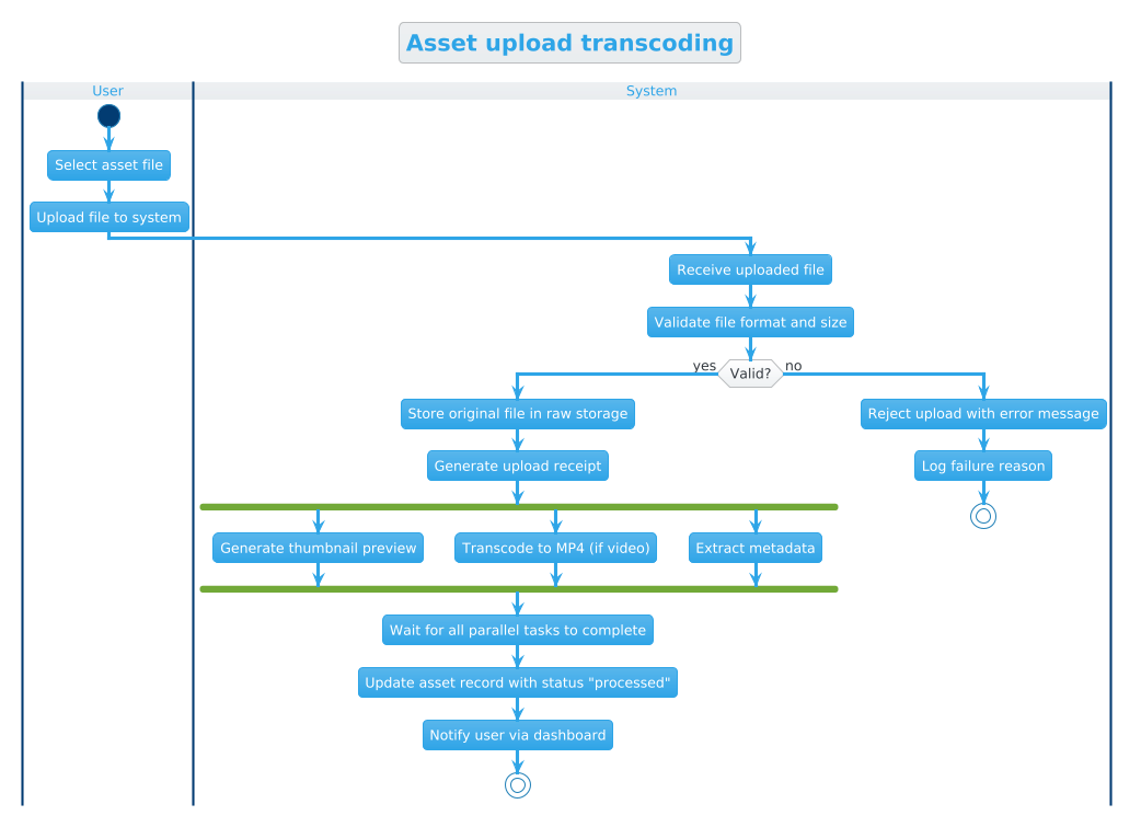
An activity diagram is the ideal notation for modeling the dynamic behavior of a system. Unlike static class diagrams, activity diagrams focus on the flow of control and data. In this specific context, we are modeling a Digital Asset Management workflow where the primary goal is to ensure that uploaded media is safe, valid, and ready for consumption.
Diagram Abstraction & Representation: This model uses swimlanes to separate responsibilities between the User and the System. This distinction is critical in system design to clarify who initiates an action and who performs backend processing. The diagram captures the entire lifecycle from file selection to final status notification, highlighting where the system must make decisions (validation) and where it can perform work simultaneously (transcoding).
Target Domain Scope & Scenario: The scope is limited to the ingestion and processing phase of the asset lifecycle. We are not modeling the user login or the final playback experience, but rather the critical backend pipeline that transforms raw data into usable assets. This includes validation checks, storage operations, and parallel processing tasks like thumbnail generation and metadata extraction.
Key Takeaways & Educational Insights: By building this diagram, you will learn how to represent branching logic (valid vs. invalid files) and concurrent operations (forking tasks) within a single flow. You will also gain insights into how to structure swimlanes to maintain readability in complex enterprise workflows.
Complete Diagram & Full Source Code
Below is the finalized blueprint for the Asset Upload Transcoding workflow. This diagram utilizes the cerulean theme for a clean, professional appearance and leverages PlantUML’s activity diagram syntax to define the logic.
@startuml
!theme cerulean
title Asset upload transcoding

|User|
start
:Select asset file;
:Upload file to system;

|System|
:Receive uploaded file;
:Validate file format and size;

if (Valid?) then (yes)
  :Store original file in raw storage;
  :Generate upload receipt;
  fork
    :Generate thumbnail preview;
  fork again
    :Transcode to MP4 (if video);
  fork again
    :Extract metadata;
  end fork
  :Wait for all parallel tasks to complete;
  :Update asset record with status "processed";
  :Notify user via dashboard;
  stop
else (no)
  :Reject upload with error message;
  :Log failure reason;
  stop
endif
@endumlStep-by-Step Architectural Walkthrough
Now, let’s deconstruct the code to understand how we built this workflow. We will break the construction down into four logical phases.
Phase 1: Canvas Configuration & Layout Directives
Every PlantUML diagram begins with setup directives that define the visual style and global properties. We start by initializing the activity diagram and applying the cerulean theme, which provides a modern blue-toned aesthetic suitable for technical documentation.
We also define the diagram title to ensure it is self-descriptive when shared or embedded.
@startuml
!theme cerulean
title Asset upload transcoding
Phase 2: Declaring Core Entities, Actors, and Boundaries
The next step is establishing the swimlanes. Swimlanes are horizontal or vertical partitions that group activities by actor or system component. This visual separation helps stakeholders understand responsibility boundaries immediately.
We define two primary lanes: |User| and |System|. The User lane handles the initiation of the process, while the System lane manages the backend logic.
|User|
start
:Select asset file;
:Upload file to system;

|System|
:Receive uploaded file;
:Validate file format and size;
Phase 3: Mapping Data Flows & Key Interactions
Here we introduce the core logic of the workflow. The system must validate the incoming data before proceeding. We use the if statement to create a conditional branch based on the validation result.
If the file is valid, the system proceeds to store the file and generate a receipt. Crucially, this phase introduces parallel processing using fork. We want to generate thumbnails, transcode video, and extract metadata simultaneously to optimize performance.
if (Valid?) then (yes)
  :Store original file in raw storage;
  :Generate upload receipt;
  fork
    :Generate thumbnail preview;
  fork again
    :Transcode to MP4 (if video);
  fork again
    :Extract metadata;
  end fork
Phase 4: Grouping, Annotations & Visual Polish
The final phase handles the synchronization of parallel tasks and the termination of the workflow. After the fork block, the system must wait for all parallel threads to finish before updating the database status and notifying the user.
We also define the else branch for invalid files, ensuring the system logs the failure and stops gracefully. This ensures error handling is explicit in the design.
  :Wait for all parallel tasks to complete;
  :Update asset record with status "processed";
  :Notify user via dashboard;
  stop
else (no)
  :Reject upload with error message;
  :Log failure reason;
  stop
endif
@enduml
Syntax & Keyword Deep Dive
Understanding the specific PlantUML keywords used in this diagram is essential for replicating this pattern in other workflows. Below is a breakdown of the key syntax elements.
start: Defines the entry point of the activity flow. It must be the first action in a swimlane or the diagram.|Swimlane Name|: Creates a new partition for grouping activities. The vertical bar syntax is required to declare the lane.if (Condition) then (Path1) else (Path2) endif: Implements conditional branching. The text inside the parentheses defines the condition and the labels for the outgoing paths.fork,fork again,end fork: These keywords define parallel execution paths. Tasks defined between these tags happen concurrently rather than sequentially.stop: Marks the termination of the current flow path.title: Sets the main title displayed at the top of the rendered diagram.!theme cerulean: Applies a specific visual theme to the diagram to match your documentation style.
Best Practices & Pitfalls to Avoid
To ensure your PlantUML diagrams remain maintainable and readable, follow these architectural best practices.
1. Keep Swimlanes Balanced: Avoid creating too many swimlanes (more than 4-5). If the workflow involves too many actors, consider splitting the diagram into sub-processes or use nested activity diagrams.
2. Explicitly Define Termination Points: Always ensure every path ends with a stop keyword. An open-ended flow can lead to confusion about where the process concludes, especially in complex conditional logic.
3. Use Parallel Processing Sparingly: While fork is powerful for performance modeling, overusing it can make the diagram visually cluttered. Only parallelize tasks that are truly independent and can occur simultaneously.
4. Consistent Naming Conventions: Use clear, imperative verbs for activity labels (e.g., “Validate file” instead of “Validation”). This makes the diagram read like a story or a set of instructions.
Start Building Activity Diagrams Faster with VPasCode
Instantly render, test, and customize your PlantUML activity diagrams online with zero installation required.