Complete Guide to PlantUML Sequence Diagrams: Syntax, Examples & Best Practices

A PlantUML sequence diagram is a text-based representation of how objects or processes interact over time in a software system. By using a plain-text domain-specific language (DSL), developers can write diagram code that automatically renders into clean visual representations. If you are looking for an intuitive Sequence Diagram editor or a flexible PlantUML editor to design, document, and share system architectures, understanding PlantUML syntax is one of the fastest ways to improve your technical documentation workflow.

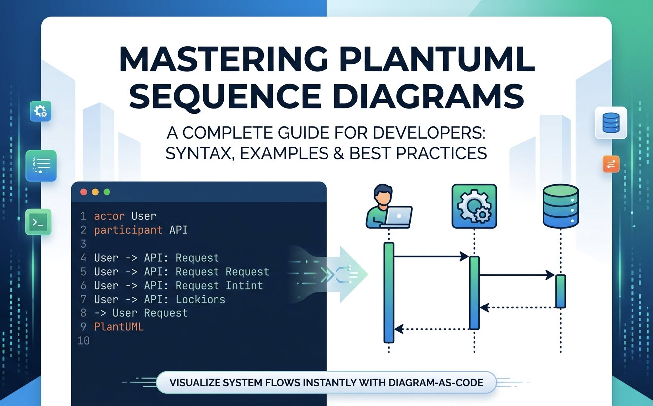
Illustrated guide banner showing a PlantUML sequence diagram code on the left transforming into a clean rendered visual workflow on the right.


What is a PlantUML Sequence Diagram? (And Why Use Diagram-as-Code)

A PlantUML sequence diagram illustrates the step-by-step exchange of messages between participants in a system during a specific execution scenario. Unlike traditional drag-and-drop design tools, PlantUML follows the Diagram-as-Code paradigm, allowing software architects and engineers to write readable script files (such as .puml) that render programmatically into diagrams.

Key Benefits: Version Control, Speed, and Consistency

  • Version Control Ready: Because diagrams exist as plain text, they can be stored in Git repositories, diffed, and merged alongside your application code.
  • Maintenance Speed: Updating a workflow takes seconds—simply edit a line of text rather than repositioning boxes and reconnecting arrows manually.
  • Visual Consistency: Rendering tools automatically calculate layout, alignment, and spacing, ensuring consistent styling across all team documentation.

Core Syntax Basics: How to Create Your First Sequence Diagram

PlantUML uses simple, human-readable keywords to define system entities and interaction paths.

Declaring Participants, Actors, and Boundaries

You can define participants explicitly using keywords that match their role in the system architecture:

@startuml
actor User
participant "API Gateway" as Gateway
database "PostgreSQL" as DB
boundary "Web App" as UI

User -> UI: Clicks Submit
UI -> Gateway: POST /api/submit
Gateway -> DB: Save Record
@enduml

Messaging and Arrows: Synchronous vs. Asynchronous Calls

The direction and appearance of arrows indicate how communication flows between components:


Syntax Visual Output Communication Type
A -> B Solid arrow with solid head Synchronous message call
A --> B Dotted arrow with solid head Response / Return message
A ->> B Solid arrow with open head Asynchronous message call
A -\ B Half-headed arrow Unidirectional / Event message

Real-World PlantUML Sequence Diagram Examples

Copy and adapt these common architectural patterns into your technical documentation.

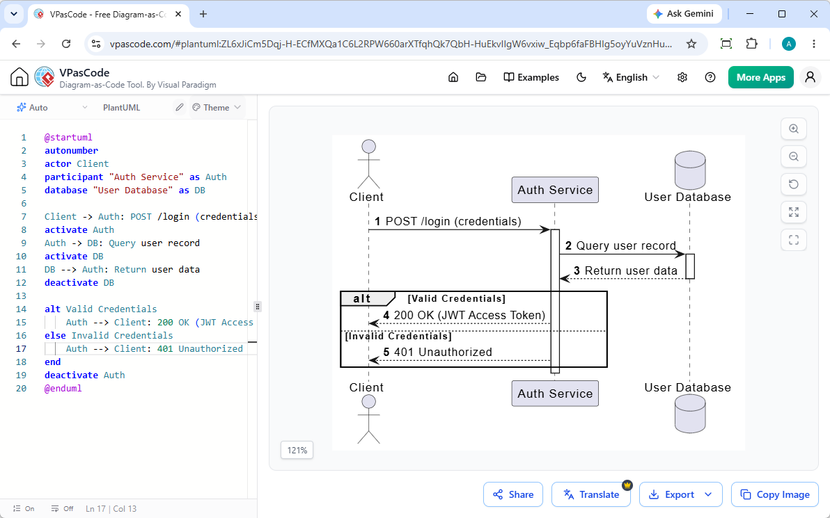
Example 1: User Authentication & JWT Token Flow

Sequence diagram example 'User Authentication & JWT Token Flow'

Corresponding PlantUML code:

@startuml
autonumber
actor Client
participant "Auth Service" as Auth
database "User Database" as DB

Client -> Auth: POST /login (credentials)
activate Auth
Auth -> DB: Query user record
activate DB
DB --> Auth: Return user data
deactivate DB

alt Valid Credentials
    Auth --> Client: 200 OK (JWT Access Token)
else Invalid Credentials
    Auth --> Client: 401 Unauthorized
end
deactivate Auth
@enduml

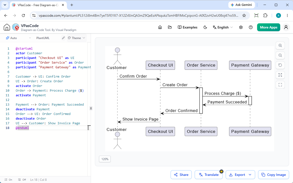
Example 2: E-Commerce Payment Gateway Integration

Sequence diagram example: 'E-Commerce Payment Gateway Integration'

Corresponding PlantUML code:

@startuml
actor Customer
participant "Checkout UI" as UI
participant "Order Service" as Order
participant "Payment Gateway" as Payment

Customer -> UI: Confirm Order
UI -> Order: Create Order
activate Order
Order -> Payment: Process Charge ($)
activate Payment

Payment --> Order: Payment Succeeded
deactivate Payment
Order --> UI: Order Confirmed
deactivate Order
UI --> Customer: Show Invoice Page
@enduml

Advanced PlantUML Features: Loops, Conditions, and Grouping

To accurately capture complex business logic, PlantUML provides built-in control structures that wrap sequences into clear visual frames.

Representing Logic with alt, opt, and loop Blocks

  • alt / else: Represents conditional branching (similar to if-else constructs).
  • opt: Represents optional steps that run only when a condition is met.
  • loop: Represents repeated interactions or polling tasks.

Activating and Deactivating Lifelines (activate / deactivate)

To clearly show when a component is actively performing work, use activate and deactivate statements, or append ++ and -- shorthand to arrow targets. This creates vertical execution bars on the participant’s lifeline, highlighting execution duration and system load.


Common PlantUML Pain Points (And How to Fix Them)

While PlantUML is immensely powerful, setting up local dependencies like Java and Graphviz can introduce unnecessary developer friction.

Fixing PlantUML Syntax Errors Without Local Java Setup

Configuring local rendering pipelines often leads to environment mismatches or missing dependency errors. Using a modern online free Sequence Diagram editor like VPasCode eliminates environment setup completely. If you run into syntax mistakes, VPasCode features built-in AI code error fixing that pinpoints invalid lines and corrects them instantly.

Exporting and Embedding Diagrams into Technical Documentation

Sharing static diagrams across technical teams often breaks documentation workflows. To keep documentation updated, export your rendered diagrams as scalable vector graphics (SVG) or high-resolution PNGs. For deeper docs integration, VPasCode connects directly with Visual Paradigm OpenDocs to maintain your diagrams natively alongside project specs.


Render and Edit PlantUML Sequence Diagrams Instantly with VPasCode

Visual Paradigm VPasCode is a unified diagram-as-code platform engineered for developers, technical writers, and software architects.

Live Preview and Automatic Format Detection

VPasCode features a zero-install browser environment equipped with automatic format detection. Simply paste your raw PlantUML, Mermaid, D2, or Graphviz script into the editor—the browser automatically identifies the language and renders a real-time interactive preview as you type.

One-Click AI Code Repair and Side-by-Side Diff Explanations

When working with dense sequence logic, typos happen. With VPasCode’s Fix by AI engine, you can resolve broken code in a single click while viewing transparent side-by-side code diffs and syntax explanations to help you master PlantUML syntax faster.


PlantUML vs. Mermaid Sequence Diagrams: Which Should You Choose?

Feature PlantUML Mermaid
Syntax Flexibility Extensive; supports advanced styling and complex constructs Streamlined; easy to learn with minimal syntax overhead
Native Ecosystem Requires Java/Graphviz for local compilation Runs natively in JavaScript-supported environments
VPasCode Support Full support with real-time browser rendering Full support with real-time browser rendering

Frequently Asked Questions (FAQ)

How do I render PlantUML without installing Java or Graphviz?

You can use a web-based PlantUML editor like VPasCode. It handles script parsing directly in the browser with live rendering—no local setup or software installations required.

Can I convert PlantUML sequence diagrams to high-resolution SVG or PNG images?

Yes. Once your script is rendered in the editor, you can export your sequence diagram as a vector SVG file for loss-free scaling, or as a crisp PNG image for presentations and documentation.

How do I share a live editable PlantUML diagram with my team?

VPasCode provides direct sharing tools, allowing you to generate shareable web links, QR codes, or publish diagrams directly to documentation hubs like Visual Paradigm OpenDocs.

滚动至顶部