


In the rapidly evolving landscape of telecommunications and internet infrastructure, DNS (Domain Name System) security is a critical pillar of network integrity. One of the most insidious threats to this infrastructure is cache poisoning, where an attacker injects false DNS records into a resolver’s cache, redirecting users to malicious sites. To combat this, modern security architectures rely on sophisticated detection systems that correlate live DNS responses with historical reputation data and cache behavior anomalies. However, designing the database schema to support such real-time monitoring requires a clear, logical blueprint that defines how resolver instances, cache entries, threat indicators, and reputation scores interact.
Building a robust detection system is not merely about writing SQL queries; it is about visualizing the data flow and entity relationships before implementation begins. An Entity-Relationship Diagram (ERD) serves as the architectural blueprint, ensuring that every piece of data—from the resolver’s IP address to the specific confidence score of a poisoning indicator—is stored and linked correctly. By using a diagram-as-code approach with PlantUML in VPasCode, architects can prototype these complex schemas instantly, validate relationships, and iterate on the design without the overhead of setting up local database environments or manual drawing tools.
Understanding the Model: Purpose, Scope & Problem Framing
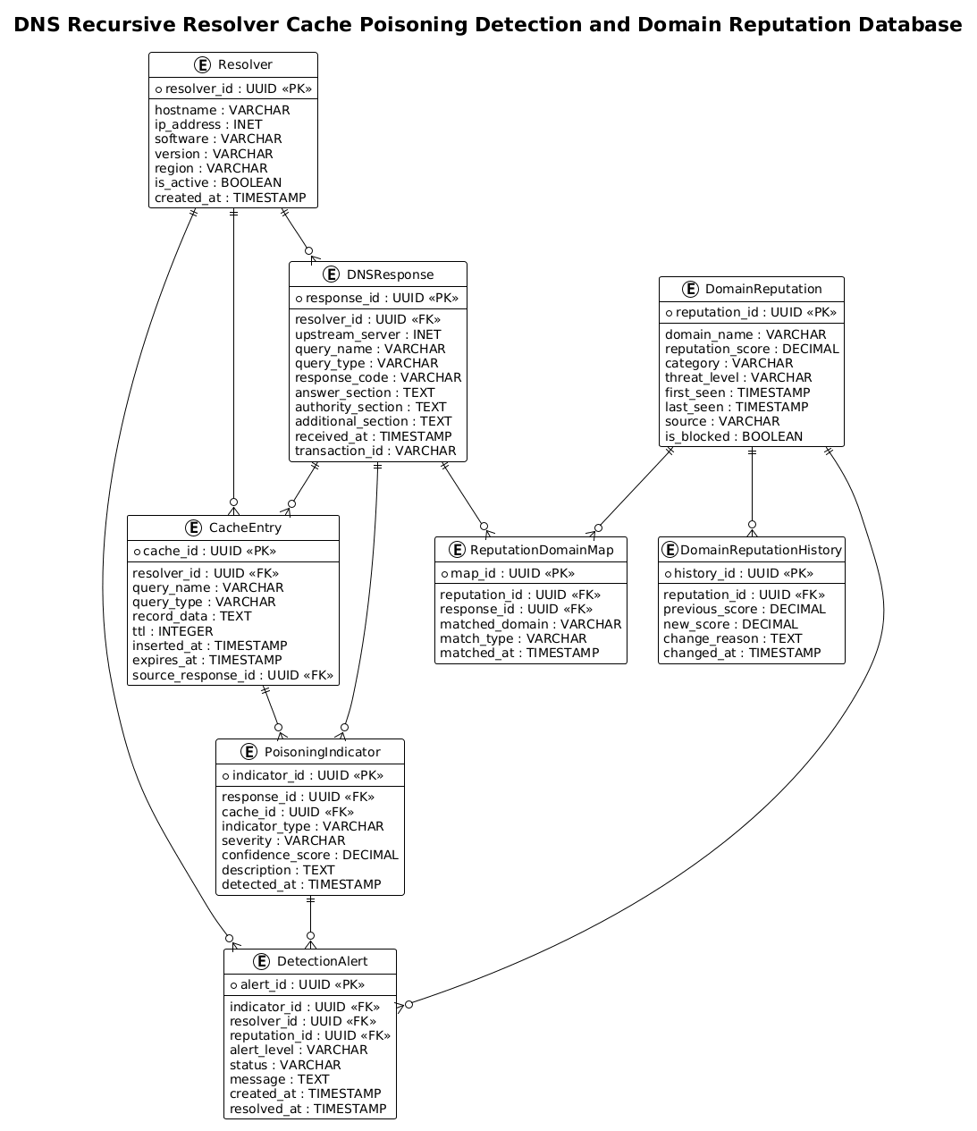
This guide focuses on constructing a specialized ERD designed for a DNS Recursive Resolver Cache Poisoning Detection and Domain Reputation Database. Unlike a standard database schema, this model is purpose-built to capture the temporal and causal relationships required for security forensics. The diagram abstracts the high-volume data generated by DNS resolvers and maps it against reputation databases to identify suspicious patterns.
Diagram Abstraction & Representation
In this ERD, we model four distinct layers of the security ecosystem:
- Operational Layer: Represented by Resolver, CacheEntry, and DNSResponse entities. These capture the raw telemetry of DNS queries, the resulting cache states, and the upstream responses that populate them.
- Threat Detection Layer: Represented by PoisoningIndicator. This entity acts as a bridge, linking a specific DNS response or cache entry to a detected anomaly, storing severity scores and confidence levels.
- Reputation Layer: Represented by DomainReputation and DomainReputationHistory. These entities track the trustworthiness of domains over time, allowing the system to correlate a suspicious response with a known threat actor or a sudden drop in reputation score.
- Alerting & Correlation Layer: Represented by DetectionAlert and ReputationDomainMap. These finalize the workflow by generating actionable alerts when the correlation logic determines a high-risk event.
Target Domain Scope & Scenario
The scope of this model is strictly defined around the telecommunications and network security domain. It covers the lifecycle of a single DNS query that triggers a poisoning detection event. It intentionally excludes external user-facing application data, focusing instead on the backend infrastructure that monitors DNS traffic. The diagram illustrates how a resolver instance (Resolver) receives a response (DNSResponse), stores it in its cache (CacheEntry), and how a detection engine flags this data (PoisoningIndicator) if it conflicts with the DomainReputation database.
Key Takeaways & Educational Insights
By studying this model, you will gain insights into:
- Temporal Data Modeling: How to link historical reputation changes to real-time events using foreign keys.
- Normalization in Security: Separating the raw response data from the threat indicators to allow for flexible analysis.
- Cardinality Management: Understanding one-to-many relationships, such as one resolver generating many cache entries, versus one-to-one relationships like a specific reputation record.
Complete Diagram & Full Source Code
Below is the finalized blueprint for the DNS Cache Poisoning Detection ERD. This diagram utilizes the !theme plain directive for a clean, professional look suitable for technical documentation. You can view the rendered result below.
@startuml
!theme plain

/'
Context: This ERD models a DNS recursive resolver cache poisoning detection and domain reputation system.
It captures how resolver instances, cache entries, DNS responses, poisoning indicators, domain reputation records,
and detection alerts relate to one another. The design supports monitoring cache behavior, scoring domain trust,
and correlating suspicious DNS responses with reputation data to identify potential cache poisoning activity.
'/

title DNS Recursive Resolver Cache Poisoning Detection and Domain Reputation Database

entity "Resolver" as resolver {
  * resolver_id : UUID <<PK>>
  --
  hostname : VARCHAR
  ip_address : INET
  software : VARCHAR
  version : VARCHAR
  region : VARCHAR
  is_active : BOOLEAN
  created_at : TIMESTAMP
}

entity "CacheEntry" as cache_entry {
  * cache_id : UUID <<PK>>
  --
  resolver_id : UUID <<FK>>
  query_name : VARCHAR
  query_type : VARCHAR
  record_data : TEXT
  ttl : INTEGER
  inserted_at : TIMESTAMP
  expires_at : TIMESTAMP
  source_response_id : UUID <<FK>>
}

entity "DNSResponse" as dns_response {
  * response_id : UUID <<PK>>
  --
  resolver_id : UUID <<FK>>
  upstream_server : INET
  query_name : VARCHAR
  query_type : VARCHAR
  response_code : VARCHAR
  answer_section : TEXT
  authority_section : TEXT
  additional_section : TEXT
  received_at : TIMESTAMP
  transaction_id : VARCHAR
}

entity "PoisoningIndicator" as poisoning_indicator {
  * indicator_id : UUID <<PK>>
  --
  response_id : UUID <<FK>>
  cache_id : UUID <<FK>>
  indicator_type : VARCHAR
  severity : VARCHAR
  confidence_score : DECIMAL
  description : TEXT
  detected_at : TIMESTAMP
}

entity "DomainReputation" as domain_reputation {
  * reputation_id : UUID <<PK>>
  --
  domain_name : VARCHAR
  reputation_score : DECIMAL
  category : VARCHAR
  threat_level : VARCHAR
  first_seen : TIMESTAMP
  last_seen : TIMESTAMP
  source : VARCHAR
  is_blocked : BOOLEAN
}

entity "DomainReputationHistory" as domain_reputation_history {
  * history_id : UUID <<PK>>
  --
  reputation_id : UUID <<FK>>
  previous_score : DECIMAL
  new_score : DECIMAL
  change_reason : TEXT
  changed_at : TIMESTAMP
}

entity "DetectionAlert" as detection_alert {
  * alert_id : UUID <<PK>>
  --
  indicator_id : UUID <<FK>>
  resolver_id : UUID <<FK>>
  reputation_id : UUID <<FK>>
  alert_level : VARCHAR
  status : VARCHAR
  message : TEXT
  created_at : TIMESTAMP
  resolved_at : TIMESTAMP
}

entity "ReputationDomainMap" as reputation_domain_map {
  * map_id : UUID <<PK>>
  --
  reputation_id : UUID <<FK>>
  response_id : UUID <<FK>>
  matched_domain : VARCHAR
  match_type : VARCHAR
  matched_at : TIMESTAMP
}

resolver ||--o{ cache_entry
resolver ||--o{ dns_response
resolver ||--o{ detection_alert
dns_response ||--o{ cache_entry
dns_response ||--o{ poisoning_indicator
cache_entry ||--o{ poisoning_indicator
poisoning_indicator ||--o{ detection_alert
domain_reputation ||--o{ domain_reputation_history
domain_reputation ||--o{ detection_alert
domain_reputation ||--o{ reputation_domain_map
dns_response ||--o{ reputation_domain_map

@endumlStep-by-Step Architectural Walkthrough
Constructing a complex ERD like this requires a structured approach. We will break down the PlantUML code into four logical phases: canvas setup, entity declaration, relationship mapping, and visual refinement.
Phase 1: Canvas Configuration & Layout Directives
Before defining any entities, we must set the stage for the diagram. In PlantUML, the @startuml directive marks the beginning of the diagram. We immediately apply the !theme plain directive to ensure the diagram renders with a clean, minimalist aesthetic, removing unnecessary decorative elements that might distract from the data structure.
We also include a comment block using the /' ... '/ syntax. This is crucial for documentation, as it allows us to embed context directly into the source code without affecting the rendering. This context block describes the operational scenario: how resolver instances interact with cache entries and how poisoning indicators are generated.
@startuml
!theme plain

/'
Context: This ERD models a DNS recursive resolver cache poisoning detection and domain reputation system.
It captures how resolver instances, cache entries, DNS responses, poisoning indicators, domain reputation records,
and detection alerts relate to one another. The design supports monitoring cache behavior, scoring domain trust,
and correlating suspicious DNS responses with reputation data to identify potential cache poisoning activity.
'/

title DNS Recursive Resolver Cache Poisoning Detection and Domain Reputation Database
Phase 2: Declaring Core Entities, Actors, and Boundaries
The core of the ERD lies in the entity blocks. We start with the Resolver, which acts as the central actor. It defines the infrastructure node (hostname, IP, software version) and uses UUID as the primary key (PK) to ensure uniqueness across distributed systems.
Next, we define the DNSResponse and CacheEntry. Notice the use of specific data types like INET for IP addresses and TIMESTAMP for tracking the lifecycle of a query. The CacheEntry includes a foreign key (FK) pointing back to the Resolver, establishing that every cache entry belongs to a specific resolver instance. Similarly, the DomainReputation entity tracks the trust score of a domain, while DomainReputationHistory stores the temporal evolution of that score.
entity "Resolver" as resolver {
* resolver_id : UUID <>
--
hostname : VARCHAR
ip_address : INET
software : VARCHAR
version : VARCHAR
region : VARCHAR
is_active : BOOLEAN
created_at : TIMESTAMP
}
entity "DNSResponse" as dns_response {
* response_id : UUID < >
--
resolver_id : UUID <>
upstream_server : INET
query_name : VARCHAR
query_type : VARCHAR
response_code : VARCHAR
answer_section : TEXT
authority_section : TEXT
additional_section : TEXT
received_at : TIMESTAMP
transaction_id : VARCHAR
}
Phase 3: Mapping Data Flows & Key Interactions
Once the entities are defined, we must establish the relationships using PlantUML’s cardinality notation. The syntax ||--o{ denotes a one-to-many relationship where the entity on the left (the “one”) can have zero or many instances on the right (the “many”).
For example, resolver ||--o{ cache_entry means one resolver can have multiple cache entries, but a cache entry belongs to exactly one resolver. We also see critical security relationships: dns_response ||--o{ poisoning_indicator links a specific response to a detected threat. This allows the system to trace a poisoning event back to the exact DNS packet that triggered it.
We also link the reputation data. domain_reputation ||--o{ detection_alert shows that a reputation record can trigger multiple alerts over time. The ReputationDomainMap acts as a junction table, linking a reputation record to a specific DNS response and the matched domain, facilitating complex cross-referencing queries.
resolver ||--o{ cache_entry
resolver ||--o{ dns_response
dns_response ||--o{ cache_entry
dns_response ||--o{ poisoning_indicator
cache_entry ||--o{ poisoning_indicator
poisoning_indicator ||--o{ detection_alert
domain_reputation ||--o{ domain_reputation_history
domain_reputation ||--o{ detection_alert
domain_reputation ||--o{ reputation_domain_map
dns_response ||--o{ reputation_domain_map
Phase 4: Grouping, Annotations & Visual Polish
While PlantUML ERD diagrams are primarily structural, we use the title directive to provide a clear header for the diagram. The entity syntax automatically groups attributes under the entity name, separated by a double hyphen (--) to distinguish keys from other fields. This visual separation helps readers quickly identify primary and foreign keys without needing to read every line of code. The final output is a cohesive map of the entire DNS security ecosystem.
Syntax & Keyword Deep Dive
To master this diagram, it is essential to understand the specific PlantUML ERD syntax elements used. These keywords define the structure, data types, and relationships.
entity: Defines a database table or entity. The syntax isentity "Name" as alias { ... }, where “Name” is the display label andaliasis the internal reference used for relationships.PKandFK: Stereotypes used to denote Primary Keys (PK) and Foreign Keys (FK). They are placed in double angle brackets like<to visually highlight the key constraints.> ||--o{: This is the cardinality notation.||represents “one and only one” (mandatory one), ando{represents “zero or many” (optional many). This specific combination indicates that the parent entity is mandatory for the child, but the child is optional./* ... */and/' ... '/: Comment blocks. The/' ... '/style is specifically used for multi-line comments that are rendered as text within the diagram context or preserved in the source for documentation.!theme: A directive to load a specific visual theme.!theme plainremoves default styling for a cleaner, more technical appearance.
Best Practices & Pitfalls to Avoid
When designing ERDs for complex systems like DNS security, following best practices ensures the diagram remains maintainable and the resulting database schema is efficient.
- Maintain Consistent Naming Conventions: Use snake_case for internal aliases (e.g.,
cache_entry) and Title Case for display names (e.g., “CacheEntry”). This distinction prevents confusion when referencing entities in the relationship lines. - Separate Concerns in Entities: Do not mix operational data (like
query_name) with metadata (likeis_active) in the same entity unless they are tightly coupled. In our model, separating DomainReputation from DomainReputationHistory allows for efficient auditing without bloating the main table. - Validate Cardinality: Double-check your relationship lines. A common pitfall is using
o{(optional) when the relationship should be mandatory (e.g., a PoisoningIndicator must always belong to a DNSResponse), which could lead to orphaned records in the database. - Use Comments for Context: Always include a comment block explaining the diagram’s purpose. As shown in this guide, a well-written comment block at the top of the PlantUML file serves as immediate documentation for future developers.
Start Building DNS Security ERDs Faster with VPasCode
Design complex database schemas for telecom and security systems instantly in your browser with VPasCode’s free PlantUML editor—no installation required.