


In modern educational technology, the admission process is a critical workflow that involves multiple systems, human actors, and data validation steps. For software architects and system designers, accurately modeling this process is essential to ensure data integrity, user experience consistency, and regulatory compliance. A complex workflow like an Admissions Processing System requires more than just a list of requirements; it demands a visual representation of the temporal interactions between components.

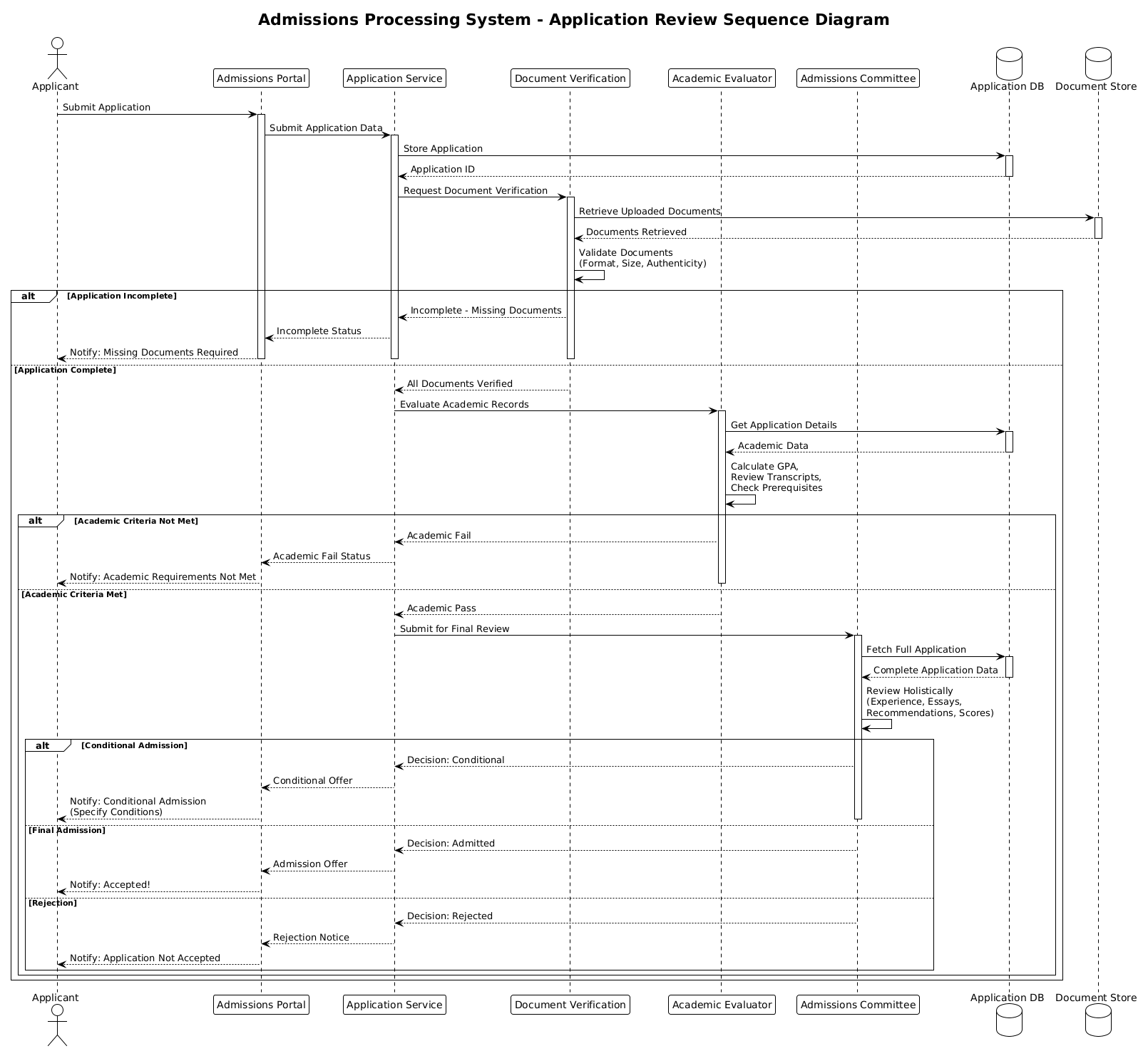
This tutorial demonstrates how to construct a professional sequence diagram using PlantUML within VPasCode. By using a diagram-as-code approach, you can maintain living documentation that evolves with your system. This specific diagram models the lifecycle of an application review, covering everything from initial submission to the final admission decision, including alternative flows for incomplete data and academic criteria checks.
Understanding the Model: Purpose, Scope & Problem Framing
Before diving into the syntax, it is crucial to understand the architectural abstraction we are modeling. A sequence diagram is the ideal tool for this scenario because it focuses on time and interaction rather than static structure.
Diagram Abstraction & Representation
This model represents the runtime behavior of the admissions system. It visualizes the lifelines (participants) and the messages (interactions) exchanged between them. Each vertical line represents an entity’s existence during the process, while horizontal arrows indicate the flow of data or commands. This abstraction helps stakeholders understand who is responsible for which task and how long a process might take based on dependencies.
Target Domain Scope & Scenario
The scope of this diagram is strictly limited to the Application Review phase of the admissions lifecycle. It intentionally excludes the user registration phase or the post-admission enrollment steps to maintain clarity. The diagram covers the following key boundaries:
- Frontend: The Applicant and the Admissions Portal.
- Backend Services: Application Service, Document Verification, and Academic Evaluator.
- Infrastructure: Application Database and Document Store.
- Human Decision Making: The Admissions Committee.
Key Takeaways & Educational Insights
By studying this model, you will gain insight into how to handle conditional logic in diagramming. You will learn how to use alt blocks to represent branching paths (e.g., incomplete vs. complete applications) without cluttering the main flow. This approach ensures your documentation remains readable even when business logic becomes complex.
Complete Diagram & Full Source Code
Below is the finished blueprint of the Admissions Processing System sequence diagram. You can view the rendered output immediately in the interactive editor.
@startuml
!theme plain
title Admissions Processing System - Application Review Sequence Diagram

/'
This sequence diagram illustrates the application review process within an
Admissions Processing System. It shows the interaction between key entities
during the review of a submitted application, including applicant document
verification, academic evaluation, and the decision-making workflow.
Alternative flows are included for incomplete applications, missing documents,
and conditional vs. final admission decisions.
'/

actor Applicant as APP
participant "Admissions Portal" as PORTAL
participant "Application Service" as APP_SVC
participant "Document Verification" as DOC_VER
participant "Academic Evaluator" as ACAD_EVAL
participant "Admissions Committee" as ADM_COMM
database "Application DB" as DB
database "Document Store" as DOC_STORE

APP -> PORTAL: Submit Application
activate PORTAL

PORTAL -> APP_SVC: Submit Application Data
activate APP_SVC

APP_SVC -> DB: Store Application
activate DB
DB --> APP_SVC: Application ID
deactivate DB

APP_SVC -> DOC_VER: Request Document Verification
activate DOC_VER

DOC_VER -> DOC_STORE: Retrieve Uploaded Documents
activate DOC_STORE
DOC_STORE --> DOC_VER: Documents Retrieved
deactivate DOC_STORE

DOC_VER -> DOC_VER: Validate Documents\n(Format, Size, Authenticity)

alt Application Incomplete
    DOC_VER --> APP_SVC: Incomplete - Missing Documents
    APP_SVC --> PORTAL: Incomplete Status
    PORTAL --> APP: Notify: Missing Documents Required
    deactivate PORTAL
    deactivate APP_SVC
    deactivate DOC_VER

else Application Complete

    DOC_VER --> APP_SVC: All Documents Verified
    deactivate DOC_VER

    APP_SVC -> ACAD_EVAL: Evaluate Academic Records
    activate ACAD_EVAL

    ACAD_EVAL -> DB: Get Application Details
    activate DB
    DB --> ACAD_EVAL: Academic Data
    deactivate DB

    ACAD_EVAL -> ACAD_EVAL: Calculate GPA,\nReview Transcripts,\nCheck Prerequisites

    alt Academic Criteria Not Met
        ACAD_EVAL --> APP_SVC: Academic Fail
        APP_SVC --> PORTAL: Academic Fail Status
        PORTAL --> APP: Notify: Academic Requirements Not Met
        deactivate PORTAL
        deactivate APP_SVC
        deactivate ACAD_EVAL

    else Academic Criteria Met
        ACAD_EVAL --> APP_SVC: Academic Pass
        deactivate ACAD_EVAL

        APP_SVC -> ADM_COMM: Submit for Final Review
        activate ADM_COMM

        ADM_COMM -> DB: Fetch Full Application
        activate DB
        DB --> ADM_COMM: Complete Application Data
        deactivate DB

        ADM_COMM -> ADM_COMM: Review Holistically\n(Experience, Essays,\nRecommendations, Scores)

        alt Conditional Admission
            ADM_COMM --> APP_SVC: Decision: Conditional
            APP_SVC --> PORTAL: Conditional Offer
            PORTAL --> APP: Notify: Conditional Admission\n(Specify Conditions)
            deactivate PORTAL
            deactivate APP_SVC
            deactivate ADM_COMM

        else Final Admission
            ADM_COMM --> APP_SVC: Decision: Admitted
            APP_SVC --> PORTAL: Admission Offer
            PORTAL --> APP: Notify: Accepted!
            deactivate PORTAL
            deactivate APP_SVC
            deactivate ADM_COMM

        else Rejection
            ADM_COMM --> APP_SVC: Decision: Rejected
            APP_SVC --> PORTAL: Rejection Notice
            PORTAL --> APP: Notify: Application Not Accepted
            deactivate PORTAL
            deactivate APP_SVC
            deactivate ADM_COMM

        end
    end
end
@endumlStep-by-Step Architectural Walkthrough
Now that you have seen the final result, let’s break down how to build this diagram from scratch using VPasCode. We will follow a logical construction order to ensure your code remains clean and maintainable.
Phase 1: Canvas Configuration & Layout Directives
Every PlantUML diagram begins with configuration directives that set the global appearance and metadata. In this scenario, we define the theme and the title to ensure the diagram looks professional immediately.
First, we apply the !theme plain directive. This removes heavy styling and provides a clean, standard look suitable for technical documentation. Next, we add the title directive to name the diagram. Finally, we wrap the description in a comment block using /' and '/ to provide context for anyone reading the source code later.
!theme plain
title Admissions Processing System - Application Review Sequence Diagram

/'
This sequence diagram illustrates the application review process within an
Admissions Processing System...
'/
Phase 2: Declaring Core Entities, Actors, and Boundaries
Before drawing connections, we must define the participants. PlantUML distinguishes between different types of entities using specific keywords. This makes the diagram self-documenting.
actor: Represents a human user (the Applicant).participant: Represents a software component or service (e.g., Admissions Portal, Application Service).database: Represents persistent storage (e.g., Application DB, Document Store).
We assign aliases (e.g., as APP) to these entities to keep the message labels concise. This is a best practice for maintaining readability in complex diagrams.
actor Applicant as APP
participant "Admissions Portal" as PORTAL
participant "Application Service" as APP_SVC
database "Application DB" as DB
Phase 3: Mapping Data Flows & Key Interactions
Once the actors are defined, we draw the primary flow using solid arrows (->) for synchronous calls and dashed arrows (-->) for return messages. We also use activate and deactivate to show when a participant is processing a task.
For example, when the Applicant submits data, the Portal is activated. The Portal then calls the Application Service, which stores data in the Database. The Database returns an ID before deactivating.
APP -> PORTAL: Submit Application
activate PORTAL

PORTAL -> APP_SVC: Submit Application Data
activate APP_SVC

APP_SVC -> DB: Store Application
activate DB
DB --> APP_SVC: Application ID
debactivate DB
Phase 4: Grouping, Annotations & Visual Polish
Real-world systems rarely follow a single linear path. To handle scenarios like missing documents or academic failures, we use alt blocks. This groups alternative flows logically.
We nest alt blocks to create complex decision trees. For instance, inside the “Application Complete” flow, we check academic criteria. If met, we proceed to the Admissions Committee. The committee then has three possible outcomes: Conditional Admission, Final Admission, or Rejection. Each outcome has its own nested alt block.
alt Application Incomplete
    DOC_VER --> APP_SVC: Incomplete - Missing Documents
    ...
else Application Complete
    ...
    alt Academic Criteria Not Met
        ...
    else Academic Criteria Met
        ...
    end
end
Syntax & Keyword Deep Dive
Understanding the specific PlantUML syntax used in this diagram is essential for mastering sequence modeling. Below are the key keywords and conventions employed:
actor: Defines a human user or external entity interacting with the system. In this diagram, it represents the Applicant.participant: Defines a software component, service, or interface. Used here for the Admissions Portal and Application Service.database: Explicitly labels storage components, helping differentiate between processing logic and data persistence.->(Solid Arrow): Represents a synchronous message or method call. The sender waits for a response.-->(Dashed Arrow): Represents a return message or an asynchronous response. Used for data retrieval (e.g.,DB --> APP_SVC).activate/deactivate: These keywords control the visual representation of the participant’s lifeline.activatestarts the execution bar, anddeactivateends it, clearly showing processing duration.alt/else/end: These keywords create combined fragments.altstarts an alternative flow group,elsedefines a different condition, andendcloses the group. This allows for representing conditional logic without breaking the diagram’s flow.
Best Practices & Pitfalls to Avoid
To create maintainable and professional diagrams, follow these modeling guidelines:
- Keep Names Consistent: Always use the same alias for an entity throughout the diagram. Switching between
APPandApplicantin the same message flow creates confusion. - Limit Nesting Depth: While PlantUML allows deep nesting of
altblocks, try to keep your logic flat where possible. If you have too many nested conditions, consider splitting the diagram into multiple views (e.g., one for Document Verification, one for Academic Evaluation). - Use Descriptive Labels: Message labels should be concise but informative. Instead of just
Send, useSubmit Application. This makes the diagram readable without needing external documentation. - Manage Lifeline Activation: Always pair
activatewithdeactivate. An unbalanced activation bar can make the diagram look messy and imply the process never completes.