


In the modern educational technology landscape, Student Information Systems (SIS) serve as the backbone for academic administration. These systems must handle complex workflows involving students, web portals, backend services, and data storage. One of the most critical workflows in any SIS is the assignment submission process. This is not merely a file upload; it is a multi-stage transaction involving validation, plagiarism screening, and automated grading.

Visualizing this workflow is essential for software architects and developers. A sequence diagram provides a temporal view of interactions between system components, clarifying the order of operations and error handling. By using PlantUML within VPasCode, architects can rapidly prototype these interactions, test logic flows, and generate living documentation without the overhead of manual drawing tools. This tutorial demonstrates how to model a production-grade assignment submission sequence diagram, complete with validation logic, alternative flows, and database persistence.
Understanding the Model: Purpose, Scope & Problem Framing
Before writing code, it is crucial to understand the modeling abstraction. A sequence diagram is not just a picture of buttons and clicks; it represents the runtime behavior of a system.
Diagram Abstraction & Representation
In this specific model, we focus on temporal interactions. We are mapping the lifecycle of a single assignment submission event. The diagram uses lifelines to represent active participants (like the Student or the Assignment Service) and activation bars to show when a participant is actively processing a request. This visualizes concurrency and resource usage.
Target Domain Scope & Scenario
This model covers the boundary between the user interface (SIS Web Portal) and the core backend logic. It intentionally includes:
- Frontend Validation: Ensuring file integrity before transmission.
- Backend Processing: Storage, plagiarism checks, and grading engines.
- Data Persistence: Interaction with the Assignment Database and Plagiarism Database.
- Error Handling: Explicit paths for invalid files and plagiarism violations.
Key Takeaways & Educational Insights
By building this diagram, you will gain insight into:
- State Transitions: How an assignment moves from
PENDINGtoSUBMITTED. - Service Boundaries: Where the responsibility shifts from the Portal to the Assignment Service.
- Conditional Logic: How to visually represent
altandelseblocks for robust system design.
Complete Diagram & Full Source Code
Below is the finished blueprint. This diagram illustrates the complete lifecycle of an assignment submission, including the critical plagiarism check and the final grade computation. You can copy the code below to test it immediately in the VPasCode editor.
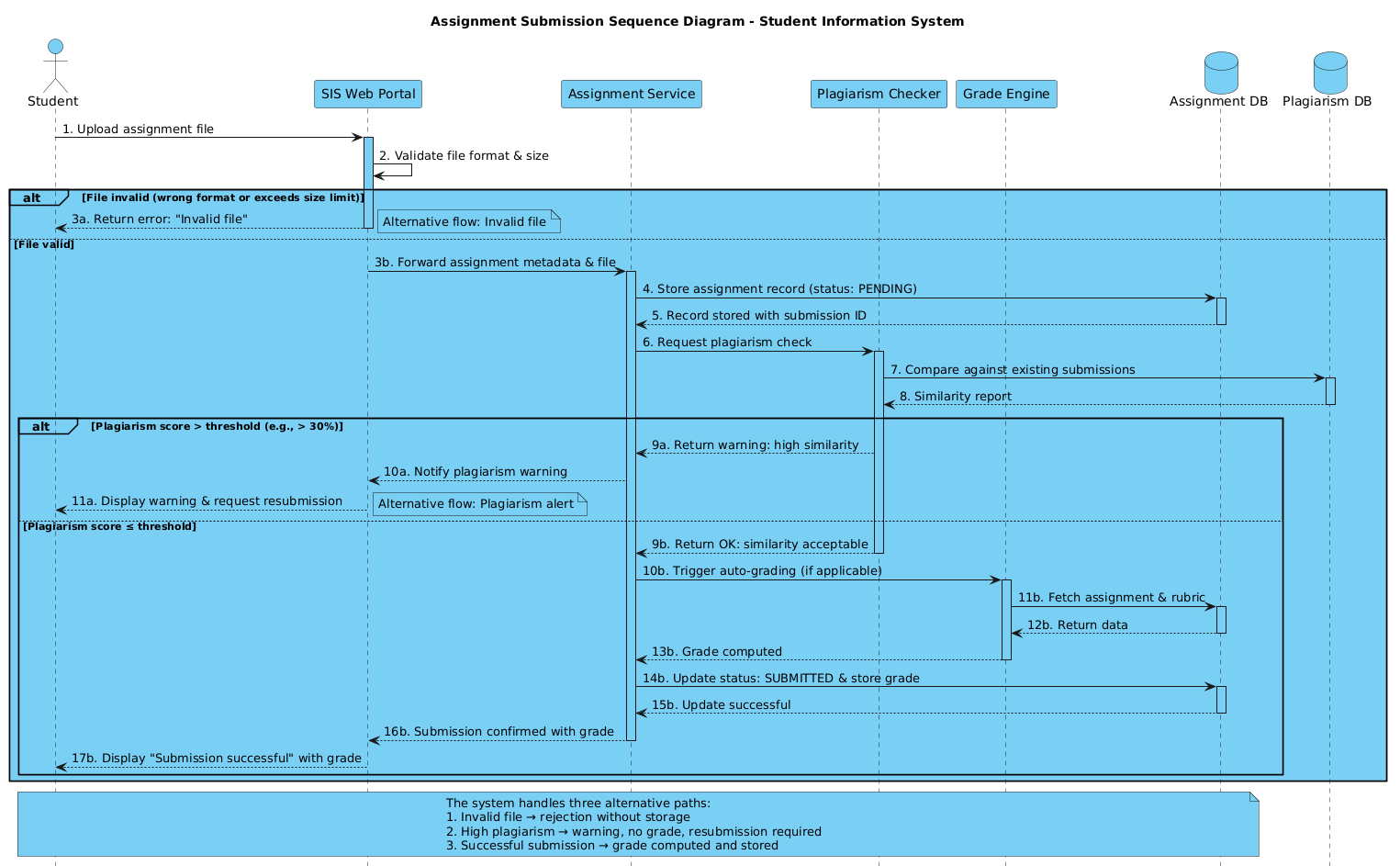
@startuml
!include https://static.visual-paradigm.com/web/resources/plantuml-stdlib/themes/vp.puml

title Assignment Submission Sequence Diagram - Student Information System

/'
This sequence diagram illustrates the assignment submission process in a Student Information System.
It covers the flow from a student uploading an assignment to receiving final confirmation,
including validation checks, plagiarism screening, and grade computation.
Alternative flows for invalid submissions, plagiarism warnings, and system errors are included.
'/

actor "Student" as S
participant "SIS Web Portal" as Portal
participant "Assignment Service" as AS
participant "Plagiarism Checker" as PC
participant "Grade Engine" as GE
database "Assignment DB" as DB
database "Plagiarism DB" as PDB

S -> Portal: 1. Upload assignment file
activate Portal

Portal -> Portal: 2. Validate file format & size

alt File invalid (wrong format or exceeds size limit)
    Portal --> S: 3a. Return error: "Invalid file"
    deactivate Portal
    note right: Alternative flow: Invalid file
else File valid
    Portal -> AS: 3b. Forward assignment metadata & file
    activate AS

    AS -> DB: 4. Store assignment record (status: PENDING)
    activate DB
    DB --> AS: 5. Record stored with submission ID
    deactivate DB

    AS -> PC: 6. Request plagiarism check
    activate PC

    PC -> PDB: 7. Compare against existing submissions
    activate PDB
    PDB --> PC: 8. Similarity report
    deactivate PDB

    alt Plagiarism score > threshold (e.g., > 30%)
        PC --> AS: 9a. Return warning: high similarity
        AS --> Portal: 10a. Notify plagiarism warning
        Portal --> S: 11a. Display warning & request resubmission
        deactivate Portal
        note right: Alternative flow: Plagiarism alert
    else Plagiarism score ≤ threshold
        PC --> AS: 9b. Return OK: similarity acceptable
        deactivate PC

        AS -> GE: 10b. Trigger auto-grading (if applicable)
        activate GE
        GE -> DB: 11b. Fetch assignment & rubric
        activate DB
        DB --> GE: 12b. Return data
        deactivate DB
        GE --> AS: 13b. Grade computed
        deactivate GE

        AS -> DB: 14b. Update status: SUBMITTED & store grade
        activate DB
        DB --> AS: 15b. Update successful
        deactivate DB

        AS --> Portal: 16b. Submission confirmed with grade
        deactivate AS
        Portal --> S: 17b. Display "Submission successful" with grade
        deactivate Portal
    end
end

note over S, DB
  The system handles three alternative paths:
  1. Invalid file → rejection without storage
  2. High plagiarism → warning, no grade, resubmission required
  3. Successful submission → grade computed and stored
end note
@endumlStep-by-Step Architectural Walkthrough
Now that you have the full diagram, let’s break down how to construct it logically. We will build this in four distinct phases.
Phase 1: Canvas Configuration & Layout Directives
Every professional diagram starts with proper setup. We begin by including a theme to ensure the diagram looks modern and consistent with standard design systems.
In the code, this is handled by the !include directive. We also set a clear title and add a descriptive comment block to document the diagram’s intent for future maintainers.
!include https://static.visual-paradigm.com/web/resources/plantuml-stdlib/themes/vp.puml

title Assignment Submission Sequence Diagram - Student Information System

/'
This sequence diagram illustrates the assignment submission process...
'/
Phase 2: Declaring Core Entities, Actors, and Boundaries
Next, we define the participants. In a sequence diagram, these are the lifelines that will exchange messages. We use specific stereotypes to denote the type of participant:
actor: Represents the human user (Student).participant: Represents software services or UI components (Portal, Service).database: Represents persistent storage layers.
actor "Student" as S
participant "SIS Web Portal" as Portal
participant "Assignment Service" as AS
database "Assignment DB" as DB
Phase 3: Mapping Data Flows & Key Interactions
This is the core logic. We draw arrows to represent messages. A solid arrow (->) indicates a synchronous call, while a dashed arrow (-->) indicates a return message. We also use activate and deactivate to show when a component is busy processing.
S -> Portal: 1. Upload assignment file
activate Portal

Portal -> Portal: 2. Validate file format & size
Portal --> S: 3a. Return error: "Invalid file"
deactivate Portal
Phase 4: Grouping, Annotations & Visual Polish
Real-world systems have exceptions. We use alt (alternative) blocks to handle branching logic, such as invalid files or plagiarism detection. Finally, we add note blocks to summarize complex paths for quick reading.
alt Plagiarism score > threshold
    ... (warning flow) ...
else Plagiarism score ≤ threshold
    ... (success flow) ...
end

note over S, DB
  The system handles three alternative paths...
end note
Syntax & Keyword Deep Dive
To master PlantUML, you must understand the specific keywords that control the diagram’s behavior. Here is a breakdown of the critical syntax used in this assignment submission model:
actor: Defines a human role interacting with the system. Used here for theStudent.participant: Defines a software component, service, or UI element. Used for thePortalandAssignment Service.database: Defines a storage entity. Used forAssignment DBandPlagiarism DB.->(Solid Arrow): Represents a synchronous request or message sent from one participant to another.-->(Dashed Arrow): Represents a return message or response from the recipient back to the sender.activate/deactivate: Controls the visual representation of the activation bar (the thin rectangle on the lifeline), indicating when a participant is actively executing logic.alt/else/end: Constructs a combined fragment to represent alternative flows or conditional logic (e.g., valid vs. invalid file).note: Adds explanatory text boxes connected to specific participants or the entire diagram.
Best Practices & Pitfalls to Avoid
When creating sequence diagrams for complex systems like SIS, follow these architectural best practices:
- Keep Lifelines Logical: Ensure each lifeline represents a distinct responsibility. Avoid putting too many unrelated functions into a single participant.
- Manage Complexity with
altBlocks: Do not clutter the main flow with every possible error. Usealtblocks to isolate exception handling (like plagiarism warnings) so the happy path remains clear. - Use Clear Naming: Always use descriptive labels for messages (e.g.,
Upload assignment fileinstead of justUpload) to ensure the diagram is self-documenting. - Balance Detail: Don’t model every single internal method call. Focus on the boundary interactions between services and the database to maintain high-level clarity.
Try It Yourself with VPasCode
Start Building Sequence Diagrams Faster with VPasCode
Experience instant live browser preview, zero local installation, and interactive syntax testing for your PlantUML diagrams today.