


Architecting Trust: Modeling Secure Cash Deposits in Finance
In the high-stakes world of financial technology, clarity is not just a design preference—it is a security requirement. When customers interact with automated deposit kiosks, the system must guarantee that cash is counted accurately, transactions are recorded immutably, and errors are handled gracefully without losing funds. For software architects and business analysts, visualizing these temporal flows is critical before a single line of production code is written.

Sequence diagrams offer the perfect lens for this task. They map out the chronological exchange of messages between system components, allowing teams to validate logic paths, identify potential race conditions, and ensure compliance with financial regulations. By using a diagram-as-code approach with PlantUML inside VPasCode, architects can prototype these complex workflows instantly in the browser. This method eliminates the friction of manual drawing tools and provides a living documentation artifact that evolves alongside the software.
This masterclass walks you through building a robust Cash Deposit Sequence Diagram for a Deposit Kiosk. We will cover the setup of the visual theme, the declaration of financial actors, and the implementation of alternative flows for bill validation errors. You will learn how to structure your code to handle both successful transactions and rejection scenarios, ensuring your architecture is resilient.
Understanding the Model: Purpose, Scope & Problem Framing
Before diving into the syntax, it is essential to understand the architectural abstraction we are modeling. A sequence diagram is a behavioral model that emphasizes the order of interactions over time. In the context of a financial kiosk, this is not merely about drawing boxes and arrows; it is about defining the contract between the physical hardware and the backend banking infrastructure.
Diagram Abstraction & Representation
This specific diagram models the runtime interaction flow of a deposit transaction. It captures the lifecycle of a single deposit session from the moment a user authenticates to the final receipt generation. The diagram distinguishes between synchronous calls (waiting for a response) and asynchronous events, which is vital for understanding system latency and blocking states. For example, the Cash Validator must complete its physical count before the system proceeds, representing a blocking operation that the backend must account for.
Target Domain Scope & Scenario
The scope of this model is strictly limited to the Deposit Kiosk ecosystem. It does not cover the entire banking ledger system, but rather the interface layer where physical cash meets digital records. The scenario assumes a standard retail kiosk environment where a Customer initiates the process. The boundaries include the Kiosk User Interface (UI), the physical Cash Validator hardware, the Kiosk Controller logic, and the external Bank Backend systems. This isolation allows developers to test the integration points without needing access to the full core banking ledger.
Key Takeaways & Educational Insights
By constructing this model, you will gain clarity on three critical architectural aspects:
- Validation Logic: How to represent the decision point where bills are either accepted or rejected.
- Transaction Integrity: Ensuring the
Bank Backendrecords the deposit only after validation is complete. - Error Handling: Modeling the
alt(alternative) flow to return cash and instruct the user if a jam is detected.
Complete Diagram & Full Source Code
Below is the finished blueprint for the Cash Deposit Scenario. This code is ready to be pasted directly into the VPasCode web editor for instant rendering. The diagram utilizes the rose theme to provide a professional, polished aesthetic suitable for stakeholder presentations.
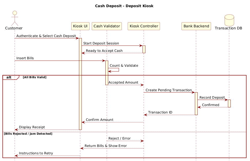
@startuml
!include https://static.visual-paradigm.com/web/resources/plantuml-stdlib/themes/rose.puml

title Cash Deposit - Deposit Kiosk

actor Customer
participant "Kiosk UI" as UI
participant "Cash Validator" as Validator
participant "Kiosk Controller" as Controller
participant "Bank Backend" as Backend
database "Transaction DB" as TxnDB

Customer -> UI ++ : Authenticate & Select Cash Deposit
UI -> Controller ++ : Start Deposit Session
Controller --> UI -- : Ready to Accept Cash
Customer -> Validator ++ : Insert Bills
Validator -> Validator : Count & Validate
alt All Bills Valid
    Validator --> Controller -- : Accepted Amount
    Controller -> Backend ++ : Create Pending Transaction
    Backend -> TxnDB ++ : Record Deposit
    TxnDB --> Backend -- : Confirmed
    Backend --> Controller -- : Transaction ID
    Controller --> UI -- : Confirm Amount
    UI --> Customer -- : Display Receipt
else Bills Rejected / Jam Detected
    Validator --> Controller -- : Reject / Error
    Controller --> UI -- : Return Bills & Show Error
    UI --> Customer -- : Instructions to Retry
end

@endumlStep-by-Step Architectural Walkthrough
Building a sequence diagram in VPasCode is an iterative process. We will break down the construction into four distinct phases: configuration, entity declaration, flow mapping, and grouping logic.
Phase 1: Canvas Configuration & Layout Directives
Every PlantUML diagram begins with setup directives that define the rendering engine and visual style. We start by opening the @startuml block, which signals the beginning of the diagram definition.
@startuml
!include https://static.visual-paradigm.com/web/resources/plantuml-stdlib/themes/rose.puml

title Cash Deposit - Deposit Kiosk
The !include directive is crucial for branding. It pulls the rose.puml theme from the Visual Paradigm repository, ensuring the diagram matches the professional aesthetic of the financial industry. The title directive provides a caption that appears above the diagram, essential for documentation context.
Phase 2: Declaring Core Entities, Actors, and Boundaries
Next, we define the participants. In a sequence diagram, these represent the lifelines that carry the messages. We use specific keywords to denote the nature of each participant.
actor Customer
participant "Kiosk UI" as UI
participant "Cash Validator" as Validator
participant "Kiosk Controller" as Controller
participant "Bank Backend" as Backend
database "Transaction DB" as TxnDB
Notice the use of actor for the human user, which renders as a stick figure. For system components, we use participant or database. We assign short aliases (like UI or Validator) to keep the message arrows concise. This separation of concerns helps visualize the boundary between the physical hardware (Validator) and the logical software (Controller).
Phase 3: Mapping Data Flows & Key Interactions
With the actors defined, we map the chronological flow. We use arrows to represent method calls or messages. The -- and ++ modifiers indicate synchronization.
Customer -> UI ++ : Authenticate & Select Cash Deposit
UI -> Controller ++ : Start Deposit Session
Controller --> UI -- : Ready to Accept Cash
The -> symbol denotes a synchronous call (the sender waits for a response), while --> denotes a return message. The ++ modifier indicates that the call is synchronous and blocking, which is critical for the Cash Validator interaction where the system cannot proceed until the cash is physically scanned.
Phase 4: Grouping, Annotations & Visual Polish
Real-world systems rarely follow a single linear path. We must handle exceptions. The alt block allows us to define alternative flows based on a condition.
alt All Bills Valid
    Validator --> Controller -- : Accepted Amount
    ... (transaction logic)
else Bills Rejected / Jam Detected
    Validator --> Controller -- : Reject / Error
    ... (error handling logic)
end
This structure ensures that if the Cash Validator detects a jam or invalid bill, the system executes the else block to return cash and display an error. This visualizes the error recovery strategy clearly for the development team.
Syntax & Keyword Deep Dive
To master PlantUML within VPasCode, you must understand the core keywords that drive the rendering engine. Here is a breakdown of the syntax features used in this Cash Deposit diagram.
@startuml/@enduml: These markers define the boundaries of the diagram definition. Anything outside these tags is ignored by the renderer.!include: Allows you to import external resources, such as themes or libraries, ensuring consistency across multiple diagrams without code duplication.actor: Renders a human stick figure. Used for external users or operators interacting with the system.participant: Renders a standard rectangle. Used for software classes, interfaces, or UI components.database: Renders a cylinder icon. Used to represent persistent storage likeTransaction DB.->vs-->: The solid line with arrow (->) is a message call. The dashed line with arrow (-->) is a return message or response.alt/else/end: These keywords create a combined fragment. They group messages that occur under specific conditions, allowing you to model branching logic like error handling.
Best Practices & Pitfalls to Avoid
When creating financial sequence diagrams in VPasCode, adhering to best practices ensures your documentation remains maintainable and clear.
- Keep Lifelines Meaningful: Avoid creating too many participants. If a component is internal to another, do not create a separate lifeline. Keep the diagram focused on the interaction boundary.
- Clear Message Naming: Use descriptive labels for arrows (e.g.,
Authenticate & Select Cash Depositinstead of justLogin). This acts as self-documenting code for the workflow. - Handle Exceptions Explicitly: Never assume a happy path. Always use
altblocks to model error states, such as network failures or hardware jams, as this is critical for financial reliability. - Consistent Theming: Use the
!includedirective to enforce a consistent visual style across all your diagrams. This makes it easier for stakeholders to recognize documentation assets.
Start Building Cash Deposit Diagrams Faster with VPasCode
Instantly render, test, and customize your PlantUML sequence diagrams in the browser with zero installation required.