


In the high-stakes world of telecommunications, the reliability of emergency call routing systems is non-negotiable. When a citizen dials an emergency number, the underlying architecture must instantly validate their identity, locate them geographically, and connect them to the correct Public Safety Answering Point (PSAP). For software architects and system designers in this sector, visualizing these critical workflows is not just about documentation—it is about ensuring life-saving reliability under pressure.

While traditional diagramming tools often require heavy installation or complex licensing, modern engineers increasingly rely on diagram-as-code methodologies. By writing code to generate diagrams, teams can diagram-as-code modeling their architectural blueprints, automate documentation updates, and ensure consistency across complex systems. VPasCode empowers you to build these mission-critical models directly in your browser, offering instant rendering and zero configuration.
Understanding the Model: Purpose, Scope & Problem Framing
This tutorial focuses on a Sequence Diagram, a specific type of UML diagram that captures the dynamic interactions between objects or components over time. In the context of a PSAP Gateway System, the primary goal is to model the temporal flow of an emergency call, from the initial dialing event to the final connection with a dispatch center.
Diagram Abstraction & Representation
A sequence diagram is the ideal tool for this scenario because it emphasizes the order of operations. Unlike a flowchart that might show decision points abstractly, a sequence diagram explicitly shows which component sends a request, which component waits, and how long a process is active (via activation bars). This temporal clarity is vital for identifying bottlenecks or race conditions in emergency systems.
Target Domain Scope & Scenario
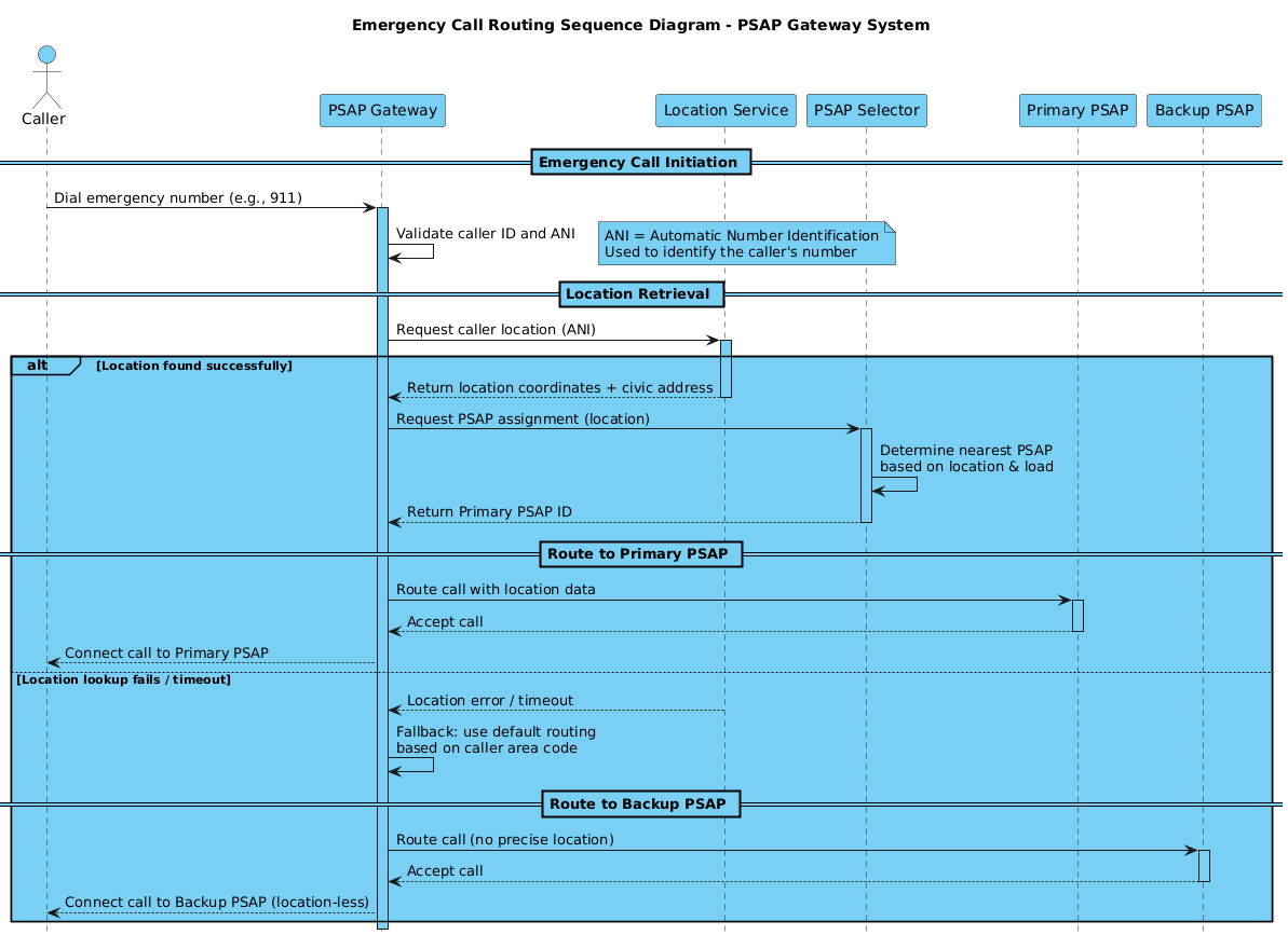
This model specifically addresses the Emergency Call Routing scenario. It defines the boundary of the PSAP Gateway as the central orchestrator. The diagram covers the critical path of locating a caller via a Location Service and routing to a Primary PSAP. Crucially, it also models the failure path (an alt fragment), ensuring the system has a fallback mechanism to route to a Backup PSAP if location data is unavailable.
Key Takeaways & Educational Insights
By constructing this model in VPasCode, you will gain insights into:
- How to structure complex conditional logic using combined fragments.
- Best practices for naming actors and participants in telecommunications systems.
- How to visually represent system activation states to highlight processing loads.
Complete Diagram & Full Source Code
Before diving into the step-by-step construction, here is the finished blueprint. This diagram demonstrates a robust emergency call flow with proper activation states and fallback handling.
Copy the complete code below to use in your own projects or to test in the VPasCode editor:
@startuml
!include https://static.visual-paradigm.com/web/resources/plantuml-stdlib/themes/vp.puml

title Emergency Call Routing Sequence Diagram - PSAP Gateway System

/'
 This sequence diagram illustrates the emergency call routing flow
 within a PSAP (Public Safety Answering Point) Gateway System.
 It covers call initiation, location validation, PSAP selection,
 and call routing with fallback handling for location lookup failures.
'/

actor "Caller" as Caller
participant "PSAP Gateway" as Gateway
participant "Location Service" as LocSvc
participant "PSAP Selector" as Selector
participant "Primary PSAP" as PrimaryPSAP
participant "Backup PSAP" as BackupPSAP

== Emergency Call Initiation ==
Caller -> Gateway : Dial emergency number (e.g., 911)
activate Gateway

Gateway -> Gateway : Validate caller ID and ANI
note right
  ANI = Automatic Number Identification
  Used to identify the caller's number
end note

== Location Retrieval ==
Gateway -> LocSvc : Request caller location (ANI)
activate LocSvc

alt Location found successfully
    LocSvc --> Gateway : Return location coordinates + civic address
    deactivate LocSvc

    Gateway -> Selector : Request PSAP assignment (location)
    activate Selector

    Selector -> Selector : Determine nearest PSAP\nbased on location & load
    Selector --> Gateway : Return Primary PSAP ID
    deactivate Selector

    == Route to Primary PSAP ==
    Gateway -> PrimaryPSAP : Route call with location data
    activate PrimaryPSAP

    PrimaryPSAP --> Gateway : Accept call
    deactivate PrimaryPSAP

    Gateway --> Caller : Connect call to Primary PSAP

else Location lookup fails / timeout
    LocSvc --> Gateway : Location error / timeout
    deactivate LocSvc

    Gateway -> Gateway : Fallback: use default routing\nbased on caller area code

    == Route to Backup PSAP ==
    Gateway -> BackupPSAP : Route call (no precise location)
    activate BackupPSAP

    BackupPSAP --> Gateway : Accept call
    deactivate BackupPSAP

    Gateway --> Caller : Connect call to Backup PSAP (location-less)
end

deactivate Gateway
@endumlStep-by-Step Architectural Walkthrough
Now, let’s deconstruct the diagram into logical phases. You can follow these steps directly in the VPasCode editor to build the model yourself.
Phase 1: Canvas Configuration & Layout Directives
Every professional PlantUML diagram starts with configuration. We begin by including the VPasCode theme to ensure consistent styling, and we define the title and description for context.
!include https://static.visual-paradigm.com/web/resources/plantuml-stdlib/themes/vp.puml

title Emergency Call Routing Sequence Diagram - PSAP Gateway System

/'
 This sequence diagram illustrates the emergency call routing flow
 within a PSAP (Public Safety Answering Point) Gateway System.
 It covers call initiation, location validation, PSAP selection,
 and call routing with fallback handling for location lookup failures.
'/
The !include directive pulls in the standard library theme, giving the diagram a modern, clean look without manual CSS work. The title command sets the header, while the comment block (wrapped in /' and '/) provides documentation that renders as a note on the diagram.
Phase 2: Declaring Core Entities, Actors, and Boundaries
Next, we define the participants. In a sequence diagram, it is crucial to distinguish between external actors (like the user) and internal system components.
actor "Caller" as Caller
participant "PSAP Gateway" as Gateway
participant "Location Service" as LocSvc
participant "PSAP Selector" as Selector
participant "Primary PSAP" as PrimaryPSAP
participant "Backup PSAP" as BackupPSAP
We use the actor keyword for the human element and participant for system services. Assigning short aliases (e.g., as Gateway) allows us to reference them concisely in the interaction flows later.
Phase 3: Mapping Data Flows & Key Interactions
With participants defined, we map the chronological flow. We start with the call initiation and then move to the complex logic of location retrieval.
== Emergency Call Initiation ==
Caller -> Gateway : Dial emergency number (e.g., 911)
activate Gateway

Gateway -> Gateway : Validate caller ID and ANI
note right
  ANI = Automatic Number Identification
  Used to identify the caller's number
end note

== Location Retrieval ==
Gateway -> LocSvc : Request caller location (ANI)
activate LocSvc
Notice the use of activate and deactivate. These create the vertical rectangles (activation bars) on the lifelines, visually indicating when a component is busy processing. The note right command adds explanatory text directly next to the component.
Phase 4: Grouping, Annotations & Visual Polish
The most critical part of this architecture is handling the failure path. We use the alt keyword to create a combined fragment, separating the success flow from the error flow.
alt Location found successfully
    LocSvc --> Gateway : Return location coordinates + civic address
    deactivate LocSvc

    Gateway -> Selector : Request PSAP assignment (location)
    activate Selector
    ...
else Location lookup fails / timeout
    LocSvc --> Gateway : Location error / timeout
    deactivate LocSvc
    ...
end
The alt block groups the logic. The else keyword defines the alternative path when the first condition fails. This visual distinction is vital for architects to quickly understand the system’s resilience strategies.
Syntax & Keyword Deep Dive
To master this diagram type, you must understand the specific PlantUML keywords used. Here is a breakdown of the core syntax features utilized in this PSAP Gateway model.
actor: Defines a human or external system interacting with the software. In this diagram, the “Caller” is the external trigger.participant: Represents a class, object, or service within the system boundary, such as the “PSAP Gateway” or “Location Service”.-->vs->: Use->for synchronous messages (the caller waits for a response) and-->for asynchronous messages (fire-and-forget or return values).activate/deactivate: Explicitly control the lifecycle bar on a lifeline. While often automatic, explicit activation is best practice for long-running processes or complex logic to prevent visual clutter.alt/else/end: These keywords create a combined fragment. They act as a decision diamond, allowing you to model conditional logic (e.g., “If location found, do X; else do Y”).note: Adds a visual annotation box to the diagram, useful for explaining abbreviations like ANI (Automatic Number Identification) without cluttering the main flow.
Best Practices & Pitfalls to Avoid
When designing sequence diagrams for critical infrastructure like emergency systems, clarity is paramount. Follow these guidelines to ensure your diagrams remain effective.
- Keep Lifelines Vertical and Consistent: Always arrange participants in a logical left-to-right order, typically from the external actor to the furthest backend service. This reduces visual scanning distance.
- Explicitly Model Failure Paths: Do not assume success. In emergency systems, fallback mechanisms (like routing to a Backup PSAP) are often more critical than the primary path. Always use
altblocks to visualize these edge cases. - Limit Message Complexity: Keep message labels concise (e.g., “Route call” instead of “Route call with all necessary location data and caller ID metadata”). Use notes for detailed explanations.
- Use Activation Bars Wisely: While PlantUML handles activations automatically, explicitly using
activateanddeactivatehelps manage long chains of interactions, preventing the lifelines from becoming a tangled mess of lines.
Try It Yourself with VPasCode
Start Building PSAP Gateway Diagrams Faster with VPasCode
Instantly render, test, and customize your emergency call routing sequence diagrams online in VPasCode without installing any tools.