


In the rapidly evolving landscape of financial technology, clarity in system requirements is paramount. For a Microfinance Management System, stakeholders must align on how various user roles interact with the core platform to ensure compliance, efficiency, and security. Traditional whiteboarding often lacks version consistency and precision, leading to miscommunication during the development phase.

This is where diagram-as-code transforms the workflow. By using PlantUML within VPasCode, architects can define system boundaries, actors, and functional goals in a text-based format that renders instantly. This approach ensures that the Use Case Diagram remains a living document, easy to update as the financial product evolves, without the friction of manual drawing tools.
Understanding the Model: Purpose, Scope & Problem Framing
Diagram Abstraction & Representation
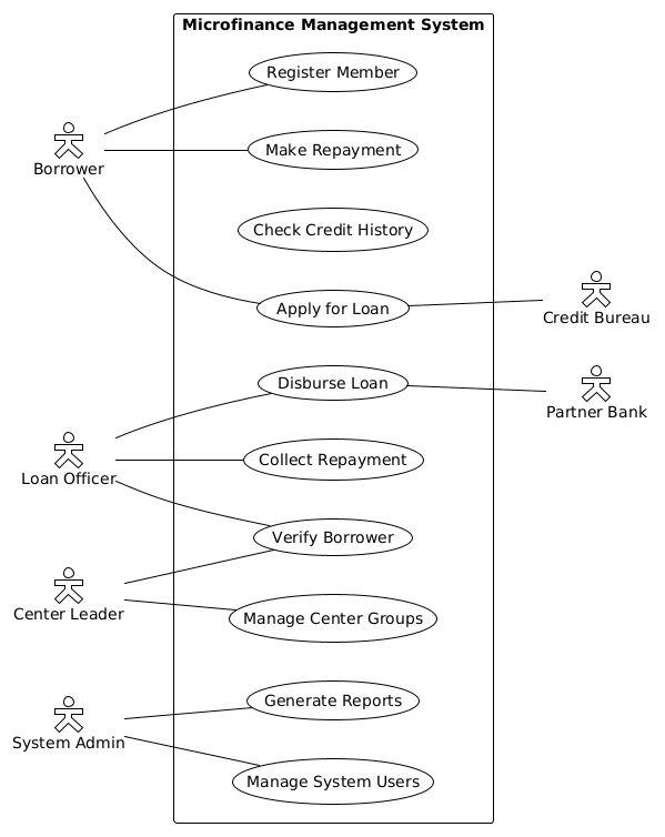
A Use Case Diagram serves as a high-level blueprint of system functionality. It does not detail internal logic or data structures; instead, it focuses on who (Actors) does what (Use Cases) within the system boundary. In the context of microfinance, this diagram clarifies the separation of duties between internal staff (Loan Officers, Admins) and external entities (Credit Bureaus, Partner Banks).
Target Domain Scope & Scenario
This model specifically addresses the Microfinance Management System. The scope includes member registration, loan lifecycle management (application to repayment), and administrative oversight. It explicitly excludes backend database schemas or API implementation details, focusing purely on user interactions and system capabilities.
Key Takeaways & Educational Insights
- Boundary Definition: Understand how to group related functionalities within a system rectangle.
- Actor Roles: Distinguish between internal users (Borrower, Admin) and external systems (Credit Bureau).
- Interaction Flows: Visualize which actors trigger specific financial processes like disbursement or verification.
Complete Diagram & Full Source Code
Below is the complete visual representation of the Microfinance Management System use case diagram, followed by the exact PlantUML source code required to generate it.
@startuml
!theme plain
left to right direction

skinparam actorStyle hollow

actor "Borrower" as borrower
actor "Loan Officer" as loanOfficer
actor "Center Leader" as centerLeader
actor "System Admin" as admin

actor "Credit Bureau" as creditBureau
actor "Partner Bank" as partnerBank

rectangle "Microfinance Management System" {
    usecase "Register Member" as UC1
    usecase "Apply for Loan" as UC2
    usecase "Verify Borrower" as UC3
    usecase "Disburse Loan" as UC4
    usecase "Make Repayment" as UC5
    usecase "Collect Repayment" as UC6
    usecase "Manage Center Groups" as UC7
    usecase "Check Credit History" as UC8
    usecase "Generate Reports" as UC9
    usecase "Manage System Users" as UC10
}

borrower -- UC1
borrower -- UC2
borrower -- UC5

centerLeader -- UC7
centerLeader -- UC3

loanOfficer -- UC3
loanOfficer -- UC4
loanOfficer -- UC6

admin -- UC9
admin -- UC10

UC2 -- creditBureau
UC4 -- partnerBank
@endumlStep-by-Step Architectural Walkthrough
Follow these phases to construct the diagram from scratch in the VPasCode web editor.
Phase 1: Canvas Configuration & Layout Directives
Begin by setting the global rendering preferences. We use the !theme plain directive to ensure a clean, professional look suitable for financial documentation. The left to right direction ensures the diagram flows horizontally, which is often better for wide architecture views.
!theme plain
left to right direction
Phase 2: Declaring Core Entities, Actors, and Boundaries
Define the external participants (Actors) and the system boundary (Rectangle). In PlantUML, actors represent roles, while the rectangle encapsulates the system scope. We assign aliases (e.g., as borrower) to make the code more readable when defining connections later.
skinparam actorStyle hollow

actor "Borrower" as borrower
actor "Loan Officer" as loanOfficer
actor "System Admin" as admin

rectangle "Microfinance Management System" {
    usecase "Register Member" as UC1
    usecase "Apply for Loan" as UC2
    // ... additional use cases
}
Phase 3: Mapping Data Flows & Key Interactions
Connect the actors to their respective use cases using the -- syntax. This line represents the interaction. For example, the Loan Officer interacts with Verify Borrower and Disburse Loan. Ensure you map the internal actors to the correct functionalities within the rectangle.
loanOfficer -- UC3
loanOfficer -- UC4
loanOfficer -- UC6
Phase 4: Grouping, Annotations & Visual Polish
Finally, include external systems that interact with specific use cases. In this finance scenario, the Apply for Loan use case connects to the Credit Bureau, and Disburse Loan connects to the Partner Bank. This highlights dependencies outside the immediate system boundary.
UC2 -- creditBureau
UC4 -- partnerBank
Syntax & Keyword Deep Dive
Mastering the specific syntax of PlantUML allows for precise control over your diagram. Here are the key keywords used in this model:
actor: Defines a human or external system interacting with the main system. Used for roles likeBorrowerorLoan Officer.usecase: Represents a specific function or goal the system performs, such asRegister Member.rectangle: Creates a boundary box to group all internal use cases, defining the system limit.--: The association line that connects actors to use cases or use cases to external systems.skinparam actorStyle hollow: A customization directive that changes the visual style of the actor icons to hollow outlines.
Best Practices & Pitfalls to Avoid
To maintain high-quality technical documentation:
- Keep Naming Consistent: Use clear, descriptive names for actors and use cases (e.g.,
"Apply for Loan"instead ofUC2in the label). - Group Logical Functions: Use the
rectangleto clearly separate internal logic from external dependencies. - Avoid Overcrowding: If a diagram becomes too complex, consider splitting it into subsystem diagrams.
- Validate Syntax Early: Use VPasCode‘s live preview to catch syntax errors immediately without local compilation.
Start Building Microfinance Use Case Diagrams Faster with VPasCode
Instantly visualize your financial system workflows in the browser. Test, preview, and customize your PlantUML diagrams online without installing any tools.