


In the complex world of telecommunications, ensuring secure and seamless connectivity for subscribers roaming across different networks is a critical challenge. The Home Location Register (HLR) and Visited Location Register (VLR) form the backbone of this process, managing subscriber profiles and authentication credentials. When a mobile device enters a foreign network, a rigorous authentication handshake must occur to verify identity before granting access to services.

Visualizing this intricate flow is essential for architects and engineers to validate security protocols and debug potential failures. While traditional diagramming tools offer drag-and-drop interfaces, diagram-as-code with PlantUML provides unparalleled precision and versioning for technical specifications. Using VPasCode, a free web-based diagram editor, you can instantly render, test, and refine these architectural blueprints without installing any local software.
This tutorial demonstrates how to construct a professional sequence diagram that models the entire lifecycle of a roaming authentication scenario, including success paths, failure handling, and retry mechanisms.
Understanding the Model: Purpose, Scope & Problem Framing
Diagram Abstraction & Representation
This model is a Sequence Diagram, a specific type of interaction diagram in the Unified Modeling Language (UML). In the context of telecommunications, sequence diagrams are the preferred method for modeling the temporal flow of messages between network elements. They capture:
- Lifelines: The distinct entities participating in the communication (MS, VLR, HLR, AuC).
- Messages: The synchronous or asynchronous signals exchanged (e.g., “Location Update Request”, “Authentication Vectors”).
- Activation Bars: Periods where an object is actively performing a task.
- Combined Fragments: Logic blocks like
alt(alternative) to represent branching paths based on conditions (e.g., Authentication Success vs. Failure).
Target Domain Scope & Scenario
The scope of this diagram is strictly limited to the Roaming Authentication Phase. It does not cover voice call setup or data session establishment after authentication. The system boundaries include:
- Mobile Station (MS): The subscriber’s device (phone).
- Visited Location Register (VLR): The database in the visited network that manages the subscriber temporarily.
- Home Location Register (HLR): The central database in the home network holding permanent subscriber data.
- Authentication Center (AuC): The secure entity responsible for generating cryptographic keys.
Key Takeaways & Educational Insights
By mastering this diagram, you will gain the ability to:
- Define clear actor boundaries and participant roles in a distributed system.
- Model complex logic flows using nested conditional fragments.
- Visualize cryptographic exchanges (RAND, SRES, Ki) without exposing sensitive data.
- Document error handling paths (retries, rejections) for robust system design.
Complete Diagram & Full Source Code
Below is the complete blueprint for the Mobile Roaming Authentication Scenario. This diagram utilizes the aws-orange theme for a clean, modern look and includes detailed comments explaining the flow.
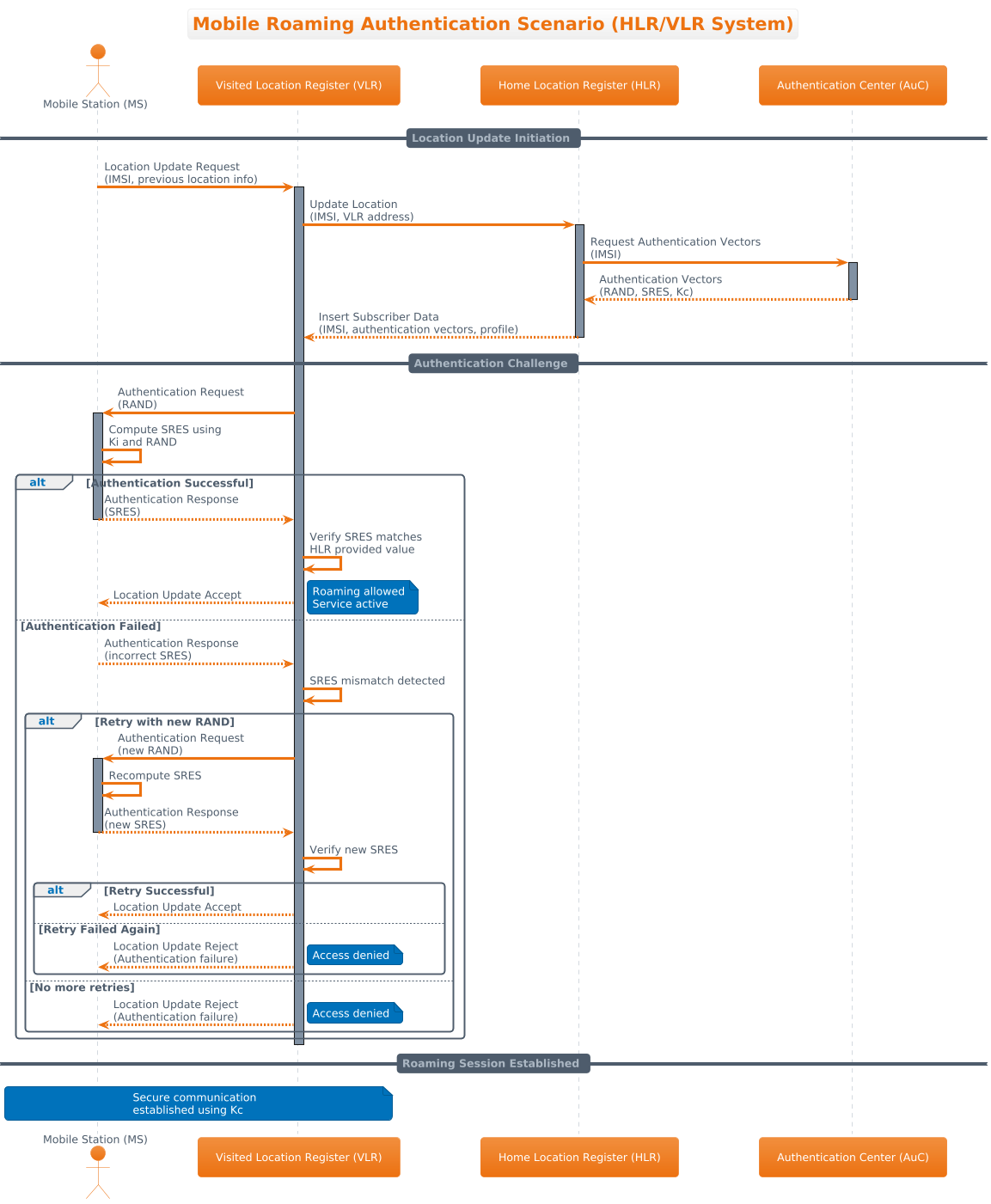
@startuml
!theme aws-orange

title Mobile Roaming Authentication Scenario (HLR/VLR System)

/'
  This sequence diagram illustrates the mobile roaming authentication process
  between a Mobile Station (MS), Visited Location Register (VLR), Home Location Register (HLR),
  and Authentication Center (AuC) when a subscriber roams into a foreign network.

  The flow includes:
  - Location update request from MS to VLR
  - Authentication data request from VLR to HLR/AuC
  - Authentication challenge-response mechanism
  - Alternative flows for authentication success and failure cases
'/

actor "Mobile Station (MS)" as MS
participant "Visited Location Register (VLR)" as VLR
participant "Home Location Register (HLR)" as HLR
participant "Authentication Center (AuC)" as AuC

== Location Update Initiation ==

MS -> VLR: Location Update Request\n(IMSI, previous location info)
activate VLR

VLR -> HLR: Update Location\n(IMSI, VLR address)
activate HLR

HLR -> AuC: Request Authentication Vectors\n(IMSI)
activate AuC

AuC --> HLR: Authentication Vectors\n(RAND, SRES, Kc)
deactivate AuC

HLR --> VLR: Insert Subscriber Data\n(IMSI, authentication vectors, profile)
deactivate HLR

== Authentication Challenge ==

VLR -> MS: Authentication Request\n(RAND)
activate MS

MS -> MS: Compute SRES using\nKi and RAND

alt Authentication Successful

    MS --> VLR: Authentication Response\n(SRES)
    deactivate MS

    VLR -> VLR: Verify SRES matches\nHLR provided value

    VLR --> MS: Location Update Accept
    note right: Roaming allowed\nService active

else Authentication Failed

    MS --> VLR: Authentication Response\n(incorrect SRES)
    deactivate MS

    VLR -> VLR: SRES mismatch detected

    alt Retry with new RAND

        VLR -> MS: Authentication Request\n(new RAND)
        activate MS
        MS -> MS: Recompute SRES
        MS --> VLR: Authentication Response\n(new SRES)
        deactivate MS

        VLR -> VLR: Verify new SRES

        alt Retry Successful

            VLR --> MS: Location Update Accept

        else Retry Failed Again

            VLR --> MS: Location Update Reject\n(Authentication failure)
            note right: Access denied

        end

    else No more retries

        VLR --> MS: Location Update Reject\n(Authentication failure)
        note right: Access denied

    end

end

deactivate VLR

== Roaming Session Established ==

note over MS, VLR: Secure communication\nestablished using Kc

@endumlStep-by-Step Architectural Walkthrough
Now that you have the full code, let’s break down how to build this diagram logically using VPasCode’s editor. We will approach this in four distinct phases.
Phase 1: Canvas Configuration & Layout Directives
Before defining any actors, we must set the stage. This involves declaring the diagram type, the visual theme, and the title.
- Theme: We use
!theme aws-orangeto apply a specific color palette that matches AWS-style visual standards. - Title: The
titledirective provides a clear header for the diagram. - Comments: The
/'block allows you to write multi-line documentation that is visible in the code but hidden in the rendered diagram.
!theme aws-orange

title Mobile Roaming Authentication Scenario (HLR/VLR System)

/'
  Documentation block for the diagram...
'/
Phase 2: Declaring Core Entities, Actors, and Boundaries
Next, we define the participants. In a sequence diagram, we distinguish between Actors (external initiators like users or devices) and Participants (internal system components like databases or servers).
actor "Mobile Station (MS)" as MS: Defines the external device.participant "Visited Location Register (VLR)" as VLR: Defines the local network database.participant "Home Location Register (HLR)" as HLR: Defines the home network database.participant "Authentication Center (AuC)" as AuC: Defines the security module.
actor "Mobile Station (MS)" as MS
participant "Visited Location Register (VLR)" as VLR
participant "Home Location Register (HLR)" as HLR
participant "Authentication Center (AuC)" as AuC
Phase 3: Mapping Data Flows & Key Interactions
This phase involves drawing the arrows between participants. We use solid arrows (->) for synchronous calls and dotted arrows (-->) for return messages. We also use activate and deactivate to show when a component is busy.
MS -> VLR: Location Update Request\n(IMSI, previous location info)
activate VLR

VLR -> HLR: Update Location\n(IMSI, VLR address)
activate HLR
Note the use of \n to force line breaks within message labels, keeping the diagram readable.
Phase 4: Grouping, Annotations & Visual Polish
Finally, we add the logic for success and failure paths using alt blocks. This allows us to model the decision tree of the authentication process. We also add note annotations to explain critical states, such as when roaming is allowed.
alt Authentication Successful
    MS --> VLR: Authentication Response\n(SRES)
    deactivate MS
    VLR --> MS: Location Update Accept
    note right: Roaming allowed\nService active
else Authentication Failed
    ... (failure handling logic)
end
Syntax & Keyword Deep Dive
To become proficient with PlantUML in VPasCode, you must understand the specific syntax used in this diagram.
actor: Defines an external entity that initiates or interacts with the system. Visually rendered as a stick figure.participant: Defines a system component or object. Visually rendered as a rectangle.->(Solid Arrow): Represents a synchronous message call where the sender waits for a response.-->(Dotted Arrow): Represents a return message or an asynchronous response.activate/deactivate: Controls the vertical activation bar on a lifeline, indicating the duration of an active operation.alt…else…end: Creates a combined fragment for alternative paths. This is essential for modeling conditional logic like authentication success vs. failure.note right/left/over: Adds annotation boxes to specific parts of the diagram to provide context or warnings.title: Sets the main header of the diagram.!theme: Applies a predefined color scheme (e.g.,aws-orange) to the entire diagram.
Best Practices & Pitfalls to Avoid
- Keep Lifelines Vertical: Ensure all participants are declared at the top of the diagram. Mixing declarations with flow logic can cause rendering errors.
- Use Descriptive Labels: Avoid generic labels like “Message 1”. Use specific technical terms like “Authentication Vectors (RAND, SRES, Kc)” to make the diagram self-documenting.
- Manage Nesting Complexity: While nested
altblocks are powerful, too many levels can make the diagram unreadable. Consider splitting complex flows into separate diagrams if the nesting exceeds three levels. - Escape Special Characters: If your message text contains special characters like
<or>, ensure they are properly escaped to prevent syntax errors in PlantUML.
Start Building PlantUML Diagrams Faster with VPasCode
Instantly render, edit, and customize your sequence diagrams online with zero installation required.