


In the modern retail landscape, inventory management is no longer a siloed backend task; it is the heartbeat of customer satisfaction. An Omnichannel Inventory Syncing System is critical for maintaining real-time stock accuracy across diverse sales channels, including e-commerce platforms, physical Point-of-Sale (POS) terminals, and third-party marketplaces. Without a robust synchronization architecture, retailers face the costly risks of overselling, stockouts, and fragmented customer experiences.

Designing this architecture requires clarity. A Component Diagram is the ideal visual tool to map the high-level structure, defining how independent modules like adapters, orchestrators, and engines interact. Using PlantUML within VPasCode allows architects to define these relationships as code, ensuring documentation stays synchronized with the evolving system. This approach enhances architectural clarity, enables rapid visual prototyping, and serves as living technical documentation that is easy to version and share.
Understanding the Model: Purpose, Scope & Problem Framing
Diagram Abstraction & Representation
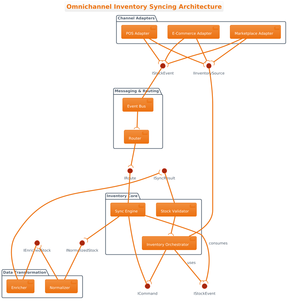
A Component Diagram in PlantUML focuses on the physical and logical building blocks of a system. Unlike sequence diagrams that show runtime interactions over time, this diagram models the static structure: which components exist, how they are grouped, and what interfaces they expose or require. The use of ball-and-socket notation (Provided and Required interfaces) clearly delineates dependencies, making it easy to identify coupling points between the Channel Adapters and the Inventory Core.
Target Domain Scope & Scenario
This model focuses specifically on the Inventory Synchronization layer of a retail ecosystem. It intentionally abstracts away the underlying database persistence and network infrastructure to focus on the logical flow of stock data. The boundaries include the ingestion of stock events from external channels (E-Commerce, POS, Marketplaces) and the internal processing required to normalize, validate, and propagate updates to the central inventory state.
Key Takeaways & Educational Insights
By constructing this model, readers will gain insights into:
- Modular Design: How to isolate channel-specific logic (Adapters) from core business rules (Orchestrator).
- Interface Contracting: The importance of defining strict input/output contracts (e.g.,
IInventorySource) to decouple components. - Data Flow: Visualizing how raw events transform into enriched stock data before validation.
Complete Diagram & Full Source Code
Below is the finished blueprint for the Omnichannel Inventory Syncing Architecture. You can view the rendered diagram immediately and edit the code directly in the VPasCode editor.
@startuml
!theme aws-orange

title Omnichannel Inventory Syncing Architecture

/'
This diagram illustrates the high-level component structure of an Omnichannel Inventory Syncing System.
The system is responsible for maintaining real-time inventory accuracy across multiple sales channels,
including e-commerce platforms, physical point-of-sale (POS) systems, and warehouse management systems.
It ensures that stock levels are consistently updated and propagated to prevent overselling, stockouts,
and discrepancies between online and offline inventory views.
'/

package "Channel Adapters" {
  [E-Commerce Adapter] as ECA
  [POS Adapter] as POSA
  [Marketplace Adapter] as MA
}

package "Inventory Core" {
  [Inventory Orchestrator] as IO
  [Stock Validator] as SV
  [Sync Engine] as SE
}

package "Messaging & Routing" {
  [Event Bus] as EB
  [Router] as R
}

package "Data Transformation" {
  [Normalizer] as N
  [Enricher] as EN
}

' Provided interfaces (ball on the left)
interface "IInventorySource" as IIS
interface "IStockEvent" as IEV
interface "ICommand" as ICMD
interface "INormalizedStock" as INS
interface "IEnrichedStock" as IES
interface "ISyncResult" as ISR
interface "IRoute" as IRT

' Required interfaces (socket on the right, using --(
ECA --( IIS
POSA --( IIS
MA --( IIS

ECA --( IEV
POSA --( IEV
MA --( IEV

IIS -- IO
IEV -- EB

EB --( R
R --( IRT
IRT -- SE

IO --( ICMD
ICMD -- SE

SE --( INS
INS -- N

N --( IES
IES -- EN

EN --( ISR
ISR -- SV

SV --( IO

' Internal required interfaces for orchestrator
IO --( IStockEvent : uses
SE --( IStockEvent : consumes

@endumlStep-by-Step Architectural Walkthrough
Phase 1: Canvas Configuration & Layout Directives
Every PlantUML diagram begins with configuration. We start by defining the theme to match the branding and setting the title for context. The comment block using /' and /' is essential for documentation, providing a human-readable summary of the system’s purpose without cluttering the rendering engine.
@startuml
!theme aws-orange

title Omnichannel Inventory Syncing Architecture

/'
This diagram illustrates the high-level component structure...
'/
Phase 2: Declaring Core Entities, Actors, and Boundaries
Next, we define the architectural boundaries using packages. In this retail scenario, we group components logically into Channel Adapters, Inventory Core, Messaging & Routing, and Data Transformation. Inside each package, we declare components using the [] syntax and assign aliases (e.g., as ECA) to simplify connection lines later.
package "Channel Adapters" {
  [E-Commerce Adapter] as ECA
  [POS Adapter] as POSA
  [Marketplace Adapter] as MA
}

package "Inventory Core" {
  [Inventory Orchestrator] as IO
  [Stock Validator] as SV
  [Sync Engine] as SE
}
Phase 3: Mapping Data Flows & Key Interactions
The core of a component diagram lies in the interface definitions. We declare interfaces (e.g., IInventorySource) as standalone elements. The relationships are then drawn using specific arrow syntax. Provided interfaces (the service offered) use a ball notation, while Required interfaces (the service needed) use a socket notation --(.
' Required interfaces (socket on the right, using --(
ECA --( IIS
POSA --( IIS
MA --( IIS

IIS -- IO
Phase 4: Grouping, Annotations & Visual Polish
Finally, we refine the diagram with internal annotations. We add labels to specific connection lines (e.g., : uses) to clarify the semantic meaning of the dependency. This phase ensures the diagram is not just a map of connections, but a readable architectural specification.
IO --( IStockEvent : uses
SE --( IStockEvent : consumes
Syntax & Keyword Deep Dive
Understanding the specific PlantUML syntax is crucial for maintaining professional diagrams. Below are the key features used in this architecture:
package "Name" { ... }: Groups components logically. Essential for managing complexity in large retail systems by separating concerns like Adapters from Core logic.[Component Name] as Alias: Defines a component shape with a shorthand identifier. Using aliases (likeIO) keeps connection lines clean and readable.interface "Name" as Alias: Declares a contract. In PlantUML, interfaces are often drawn as small rectangles or balls/sockets depending on the connection style.--(: Represents a Required Interface. The socket shape (open parenthesis) visually indicates that the component on the left needs a service from the interface on the right.--: Represents a standard dependency or connection. When connecting a component to a provided interface, the ball (circle) is automatically rendered on the interface side./' ... /': Multi-line comment syntax. This text is ignored by the renderer but is vital for documentation and context.
Best Practices & Pitfalls to Avoid
To ensure your PlantUML diagrams remain maintainable and clear, follow these architectural modeling best practices:
- Keep Diagrams Modular: Avoid placing all components in the root. Use
packagestatements to group related functionality, such as separating Adapters from the Core. - Use Consistent Naming Conventions: Use clear aliases (e.g.,
IOfor Inventory Orchestrator) and ensure interface names follow a verb or noun convention (e.g.,IInventorySource). - Manage Visual Complexity: If a diagram becomes too crowded, consider breaking it into multiple diagrams (e.g., one for Adapters, one for Core) rather than cramming everything into one view.
- Document with Comments: Use the
/'comment block to explain the diagram’s scope. This helps future developers understand the context without reading the code logic.
Try It Yourself with VPasCode
Start Building PlantUML Diagrams Faster with VPasCode
Experience instant live browser preview and zero local installation to prototype and customize your Omnichannel Inventory Syncing architecture online.