


In the modern healthcare landscape, Electronic Health Record (EHR) systems serve as the backbone of patient data management. When a patient registers for services, the system must ensure data integrity, prevent duplicates, and validate information before creating a permanent medical record. This process involves multiple layers: the user interface, business logic controllers, validation services, and persistent storage.

Visualizing this workflow is critical for software architects and developers to identify potential bottlenecks or security gaps before writing production code. Sequence diagrams are the industry standard for modeling these time-based interactions. However, maintaining these diagrams in traditional drawing tools can be cumbersome and prone to synchronization errors with code.
This masterclass demonstrates how to use PlantUML within VPasCode to create a professional, version-ready sequence diagram. By adopting a diagram-as-code approach, you gain instant live rendering, reusable templates, and the ability to integrate visual documentation directly into your technical workflow without the overhead of manual drawing.
Understanding the Model: Purpose, Scope & Problem Framing
Diagram Abstraction & Representation
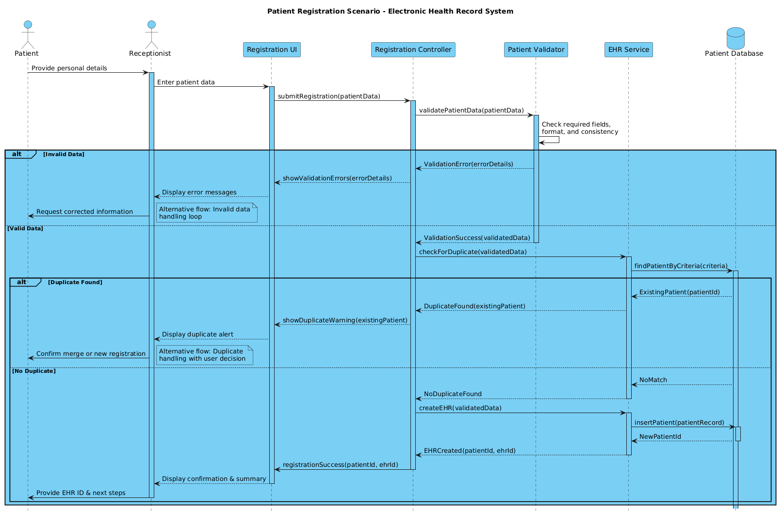
A sequence diagram captures the dynamic behavior of a system by showing how objects interact over time. In this specific model, we focus on the registration lifecycle. The diagram abstracts away the internal implementation details of the backend services to focus on the flow of control and data exchange.
- Lifelines: Represent the active participants in the process, such as the Receptionist (human actor) and the Controller (software service).
- Messages: Arrows indicate synchronous calls (solid line) or asynchronous events, showing the order of operations.
- Activation Bars: Vertical rectangles on lifelines indicate when an object is actively performing a task.
Target Domain Scope & Scenario
This diagram covers the Happy Path of patient registration, where data is valid and no duplicates exist. Crucially, it also models Alternative Flows using combined fragments:
- Invalid Data Handling: What happens if the receptionist enters an invalid email or phone number?
- Duplicate Detection: What occurs if a patient with the same details already exists in the system?
The scope is bounded to the registration module. It does not cover post-registration billing or appointment scheduling, keeping the diagram focused and maintainable.
Key Takeaways & Educational Insights
By following this guide, you will learn how to structure a healthcare workflow that prioritizes data validation before persistence. You will understand how to use PlantUML logic to handle conditional branching (alt/else blocks) and how to annotate complex flows with notes for stakeholder clarity.
Complete Diagram & Full Source Code
Below is the complete blueprint for the Patient Registration scenario. You can view the rendered result immediately in the VPasCode editor.
@startuml

!include https://static.visual-paradigm.com/web/resources/plantuml-stdlib/themes/vp.puml

title Patient Registration Scenario - Electronic Health Record System

/'
  This sequence diagram illustrates the patient registration workflow in an EHR system.
  It covers the happy path (patient data entry, validation, EHR creation, and confirmation)
  as well as alternative flows for duplicate patient detection and invalid data handling.
'/

actor "Patient" as Patient
actor "Receptionist" as Receptionist
participant "Registration UI" as UI
participant "Registration Controller" as Controller
participant "Patient Validator" as Validator
participant "EHR Service" as EHR
database "Patient Database" as DB

Patient -> Receptionist: Provide personal details
activate Receptionist

Receptionist -> UI: Enter patient data
activate UI

UI -> Controller: submitRegistration(patientData)
activate Controller

Controller -> Validator: validatePatientData(patientData)
activate Validator

Validator -> Validator: Check required fields,\nformat, and consistency
alt Invalid Data
    Validator --> Controller: ValidationError(errorDetails)
    Controller --> UI: showValidationErrors(errorDetails)
    UI --> Receptionist: Display error messages
    Receptionist -> Patient: Request corrected information
    note right: Alternative flow: Invalid data\nhandling loop

else Valid Data
    Validator --> Controller: ValidationSuccess(validatedData)
    deactivate Validator

    Controller -> EHR: checkForDuplicate(validatedData)
    activate EHR
    EHR -> DB: findPatientByCriteria(criteria)
    activate DB

    alt Duplicate Found
        DB --> EHR: ExistingPatient(patientId)
        EHR --> Controller: DuplicateFound(existingPatient)
        Controller --> UI: showDuplicateWarning(existingPatient)
        UI --> Receptionist: Display duplicate alert
        Receptionist -> Patient: Confirm merge or new registration
        note right: Alternative flow: Duplicate\nhandling with user decision

    else No Duplicate
        DB --> EHR: NoMatch
        EHR --> Controller: NoDuplicateFound
        deactivate EHR

        Controller -> EHR: createEHR(validatedData)
        activate EHR
        EHR -> DB: insertPatient(patientRecord)
        activate DB
        DB --> EHR: NewPatientId
        deactivate DB
        EHR --> Controller: EHRCreated(patientId, ehrId)
        deactivate EHR

        Controller -> UI: registrationSuccess(patientId, ehrId)
        deactivate Controller
        UI --> Receptionist: Display confirmation & summary
        deactivate UI
        Receptionist -> Patient: Provide EHR ID & next steps
        deactivate Receptionist
    end
end

@endumlStep-by-Step Architectural Walkthrough
Phase 1: Canvas Configuration & Layout Directives
Before defining entities, we configure the visual theme and metadata. Using the !include directive allows us to leverage the official VPasCode theme library for consistent styling.
!include https://static.visual-paradigm.com/web/resources/plantuml-stdlib/themes/vp.puml

title Patient Registration Scenario - Electronic Health Record System

/'
  This sequence diagram illustrates the patient registration workflow...
'/
The title directive sets the diagram header. The comment block /' ... '/ provides documentation that is hidden in the rendered diagram but visible in the source code for maintainability.
Phase 2: Declaring Core Entities, Actors, and Boundaries
Next, we define the participants. In PlantUML, we distinguish between human actors and system components.
actor "Patient" as Patient
actor "Receptionist" as Receptionist
participant "Registration UI" as UI
participant "Registration Controller" as Controller
participant "Patient Validator" as Validator
participant "EHR Service" as EHR
database "Patient Database" as DB
We use actor for external human roles. The participant keyword represents software classes or services. The database keyword specifically styles the storage layer, making it clear to stakeholders that this is a data persistence layer.
Phase 3: Mapping Data Flows & Key Interactions
Now we establish the sequence of events. We start with the human interaction and move into the system logic.
Patient -> Receptionist: Provide personal details
activate Receptionist

Receptionist -> UI: Enter patient data
activate UI

UI -> Controller: submitRegistration(patientData)
activate Controller
The -> arrow denotes a synchronous message. The activate keyword starts the vertical activation bar, indicating the participant is busy processing. We nest these calls logically: the Controller calls the Validator, which calls itself for internal checks.
Phase 4: Grouping, Annotations & Visual Polish
To handle business logic variations, we use alt blocks. This allows us to model both success and failure paths within a single diagram.
alt Invalid Data
    Validator --> Controller: ValidationError(errorDetails)
    note right: Alternative flow: Invalid data\nhandling loop

else Valid Data
    ...
The note right command adds a sticky note to the diagram, explaining the alternative flow without cluttering the main path. This is essential for healthcare compliance documentation where error handling is critical.
Syntax & Keyword Deep Dive
Understanding the specific PlantUML syntax is key to mastering diagram-as-code. Here are the critical keywords used in this healthcare model:
actor: Defines a human role interacting with the system. It renders with a stick figure icon.participant: Represents a software component, service, or class. It renders as a standard rectangle.database: Specifically styles a lifeline to look like a cylinder, indicating persistent storage.->and-->:->is a solid line for synchronous calls (wait for response).-->is a dashed line for asynchronous messages.activate/deactivate: Manually control the length of the activation bar. While often automatic, explicit control improves clarity in complex flows.alt/else/end: These keywords create a combined fragment box. They group messages that are mutually exclusive (e.g., Valid vs. Invalid data).note: Adds explanatory text to the diagram.note rightpositions the note to the right of the lifeline.
Best Practices & Pitfalls to Avoid
To maintain high-quality documentation in VPasCode, follow these architectural modeling principles:
- Keep Lifelines Consistent: Ensure the order of lifelines remains logical (e.g., Actors on the left, Database on the right) throughout the diagram to reduce cognitive load.
- Manage Visual Complexity: If a sequence diagram becomes too crowded, consider breaking it into multiple diagrams (e.g., one for “Registration”, one for “Duplicate Handling”).
- Use Meaningful Names: Avoid generic names like “Object1”. Use domain-specific terms like “EHR Service” or “Patient Validator” to align with business terminology.
- Document Alternative Flows: In healthcare, error handling is as important as the happy path. Always use
altblocks to show what happens when validation fails or duplicates are found.
Start Building PlantUML Sequence Diagrams Faster with VPasCode
Test, preview, and customize your healthcare workflow diagrams instantly in your browser with zero installation required.