


In the rapidly evolving landscape of digital healthcare, the reliability and scalability of telemedicine platforms are paramount. A Telemedicine Consultation Portal is not merely a web page; it is a complex distributed system requiring strict separation of concerns to ensure patient data security, low-latency video streaming, and robust appointment management. As systems grow, maintaining architectural clarity becomes a significant challenge for engineering teams.

Visual modeling plays a critical role in bridging the gap between abstract requirements and concrete implementation. Specifically, a Component Diagram allows architects to define the modular building blocks of the system and their interactions without getting bogged down in implementation details. By using PlantUML within VPasCode, developers can prototype these architectures instantly in the browser, ensuring that the separation between presentation, business logic, and integration layers is clearly defined before a single line of production code is written.
Understanding the Model: Purpose, Scope & Problem Framing
Before diving into the syntax, it is essential to understand the architectural abstraction being modeled. This diagram represents the structural decomposition of the Telemedicine Consultation Portal.
Diagram Abstraction & Representation
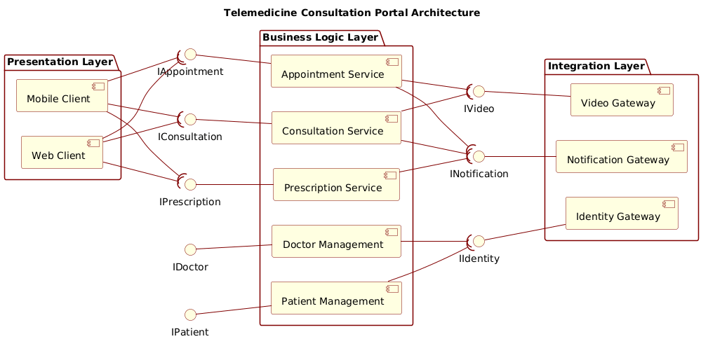
This component diagram models the system using a layered architecture pattern, a standard best practice for enterprise applications. The diagram visualizes:
- Components: Functional units (e.g.,
Consultation Service,Web Client) that encapsulate specific behaviors. - Interfaces: The explicit points of interaction between components. We use Ball-and-Socket notation to distinguish between Provided Interfaces (the services a component offers, represented by a ball) and Required Interfaces (the services a component needs, represented by a socket).
- Connections: The dependencies showing how components rely on one another to function.
Target Domain Scope & Scenario
The scope of this model covers the core transactional flow of a telemedicine session. It intentionally excludes low-level database schemas to focus on the service boundaries. The architecture is divided into three distinct packages:
- Presentation Layer: Handles user interaction via Web and Mobile clients.
- Business Logic Layer: Contains the core domain services like Appointments, Consultations, and Patient Management.
- Integration Layer: Manages external dependencies such as Video Gateways, Identity Providers, and Notification Services.
Key Takeaways & Educational Insights
By constructing this diagram, you will gain clarity on how to decouple the user interface from backend logic. You will learn how to enforce strict interface contracts using PlantUML, ensuring that the Web Client does not depend directly on the Video Gateway, but rather on the Consultation Service which provides the necessary interface. This abstraction is critical for maintainability in healthcare software where compliance and security updates are frequent.
Complete Diagram & Full Source Code
Below is the finished blueprint for the Telemedicine Consultation Portal. You can view the rendered result immediately by pasting the code below into the VPasCode editor.
@startuml
!include https://static.visual-paradigm.com/web/resources/plantuml-stdlib/themes/rose.puml

title Telemedicine Consultation Portal Architecture

/'
This component diagram illustrates the high-level architectural structure of the Telemedicine Consultation Portal.
The system enables remote patient-doctor interactions through video consultations, appointment scheduling,
prescription management, and electronic health record access. The portal integrates with external identity
providers, notification services, and video conferencing platforms. The architecture is organized into
presentation, business logic, and integration layers to support scalability, security, and maintainability.
'/

left to right direction

package "Presentation Layer" {
    component "Web Client" as Web
    component "Mobile Client" as Mobile
}

package "Business Logic Layer" {
    component "Consultation Service" as Consultation
    component "Appointment Service" as Appointment
    component "Prescription Service" as Prescription
    component "Patient Management" as PatientMgmt
    component "Doctor Management" as DoctorMgmt
}

package "Integration Layer" {
    component "Notification Gateway" as Notification
    component "Video Gateway" as Video
    component "Identity Gateway" as Identity
}

' Provided interfaces (ball on left, interface -- component)
interface "IAppointment" as IAppt
interface "IConsultation" as IConsult
interface "IPrescription" as IPrescr
interface "IPatient" as IPatient
interface "IDoctor" as IDoctor
interface "INotification" as INotif
interface "IVideo" as IVideo
interface "IIdentity" as IIdent

' Presentation Layer requires business interfaces (socket on right, component --( interface)
Web --( IAppt
Web --( IConsult
Web --( IPrescr
Mobile --( IAppt
Mobile --( IConsult
Mobile --( IPrescr

' Business Layer provided interfaces (ball on left, interface -- component)
IAppt -- Appointment
IConsult -- Consultation
IPrescr -- Prescription
IPatient -- PatientMgmt
IDoctor -- DoctorMgmt

' Business Layer requires integration interfaces (socket on right, component --( interface)
Appointment --( INotif
Appointment --( IVideo
Consultation --( IVideo
Consultation --( INotif
Prescription --( INotif
PatientMgmt --( IIdent
DoctorMgmt --( IIdent

' Integration Layer provided interfaces (ball on left, interface -- component)
INotif -- Notification
IVideo -- Video
IIdent -- Identity

@endumlStep-by-Step Architectural Walkthrough
Building a professional component diagram requires a structured approach. We will construct this diagram in four logical phases using VPasCode.
Phase 1: Canvas Configuration & Layout Directives
Before defining components, we must set the stage. We start by including a theme to ensure visual consistency and define the reading direction.
First, we include the rose.puml theme to apply a polished look:
!include https://static.visual-paradigm.com/web/resources/plantuml-stdlib/themes/rose.pumlNext, we set the orientation to left to right. This is crucial for component diagrams as it aligns with the natural flow of data from the client (left) to the backend services (right).
left to right directionWe also add a title and a comment block to document the context. The comment block starts with / and ends with ':
title Telemedicine Consultation Portal Architecture

/'
This component diagram illustrates the high-level architectural structure...
'/
Phase 2: Declaring Core Entities, Actors, and Boundaries
Next, we define the structural boundaries using package statements. This groups components logically, which is essential for managing complexity in large systems.
We create three packages corresponding to our architectural layers:
package "Presentation Layer" {
    component "Web Client" as Web
    component "Mobile Client" as Mobile
}

package "Business Logic Layer" {
    component "Consultation Service" as Consultation
    ...
}

package "Integration Layer" {
    component "Notification Gateway" as Notification
    ...
}
Each component represents a deployable unit. We assign short aliases (e.g., as Web) to keep the diagram clean and the code concise.
Phase 3: Mapping Data Flows & Key Interactions
This is the core of the component diagram: defining how layers communicate via interfaces. We use the Ball-and-Socket notation.
Provided Interfaces (Ball): Represented by interfaceName -- ComponentName. The ball (circle) is on the left side of the line, indicating the interface is provided by the component on the right.
IAppt -- AppointmentRequired Interfaces (Socket): Represented by ComponentName --( interfaceName. The socket (bracket) is on the right side of the line, indicating the component on the left requires the interface on the right.
Web --( IApptWe map these relationships across the layers. For instance, the Appointment Service requires the INotification interface to send alerts, while the Notification Gateway provides it.
Phase 4: Grouping, Annotations & Visual Polish
Finally, we ensure all components are correctly grouped within their packages. We verify that the Integration Layer does not expose internal logic to the Presentation Layer. The architecture enforces a strict dependency rule: Presentation depends on Business, and Business depends on Integration. This separation ensures that changes in the video provider (Integration) do not break the web client (Presentation).
Syntax & Keyword Deep Dive
Understanding the specific PlantUML syntax used here is key to mastering component modeling.
package: Used to group components. It acts as a logical container for related services, helping to organize the diagram visually.component: Defines a functional unit. It can represent a microservice, a library, or a class.interface: Defines a contract. It specifies a set of operations that a component can perform or requires from another.--: The standard dependency arrow. When used asinterface -- component, it denotes a Provided Interface (Ball on left).--(: The required interface arrow. The(symbol creates a socket shape on the right side of the line, indicating Required Interface.!include: Allows importing external themes or libraries. Here, it loads therose.pumltheme for styling./…': The syntax for a multi-line comment block. This is used for documentation within the code itself.
Best Practices & Pitfalls to Avoid
To maintain a high-quality architectural model, follow these guidelines:
- Keep Interfaces Abstract: Do not expose implementation details through interfaces. Define
IAppointmentas a contract, not a list of database queries. - Enforce Layering: Ensure that components in the
Presentation Layernever directly access theIntegration Layer. They must go through theBusiness Logic Layer. - Use Clear Naming: Use prefixes like
Ifor interfaces (e.g.,IConsultation) to visually distinguish them from components immediately. - Limit Scope: A component diagram should not contain every single class. Focus on the major subsystems and their interactions.
Start Building Telemedicine Component Diagrams Faster with VPasCode
Design and render professional healthcare architecture diagrams instantly in your browser with VPasCode’s free PlantUML editor.