


Architectural Context: Modeling Civic Identity Workflows
In the realm of government technology and civic identity management, clarity is not just a design preference—it is a legal and operational imperative. When designing a Civic Identity Management System, the workflow for voter registration verification must be robust, auditable, and transparent. A single point of confusion in the registration process can lead to significant delays, disenfranchisement, or security vulnerabilities.
This tutorial demonstrates how to model a complex activity diagram for a Voter Registration Verification Process using PlantUML within VPasCode. By leveraging diagram-as-code, architects can define precise swimlanes, parallel processing paths, and conditional logic that mirrors real-world system interactions. VPasCode allows you to visualize these workflows instantly in the browser, ensuring that stakeholders—from system architects to compliance officers—share a unified understanding of the verification lifecycle before a single line of backend code is written.
Understanding the Model: Purpose, Scope & Problem Framing
Before diving into the syntax, it is essential to understand the architectural abstraction we are building. This activity diagram represents the lifecycle of a voter registration application as it moves through a government-managed system.
Diagram Abstraction & Representation
We are using an activity diagram because the primary focus is on process flow rather than data structure or class relationships. This diagram type is ideal for visualizing:
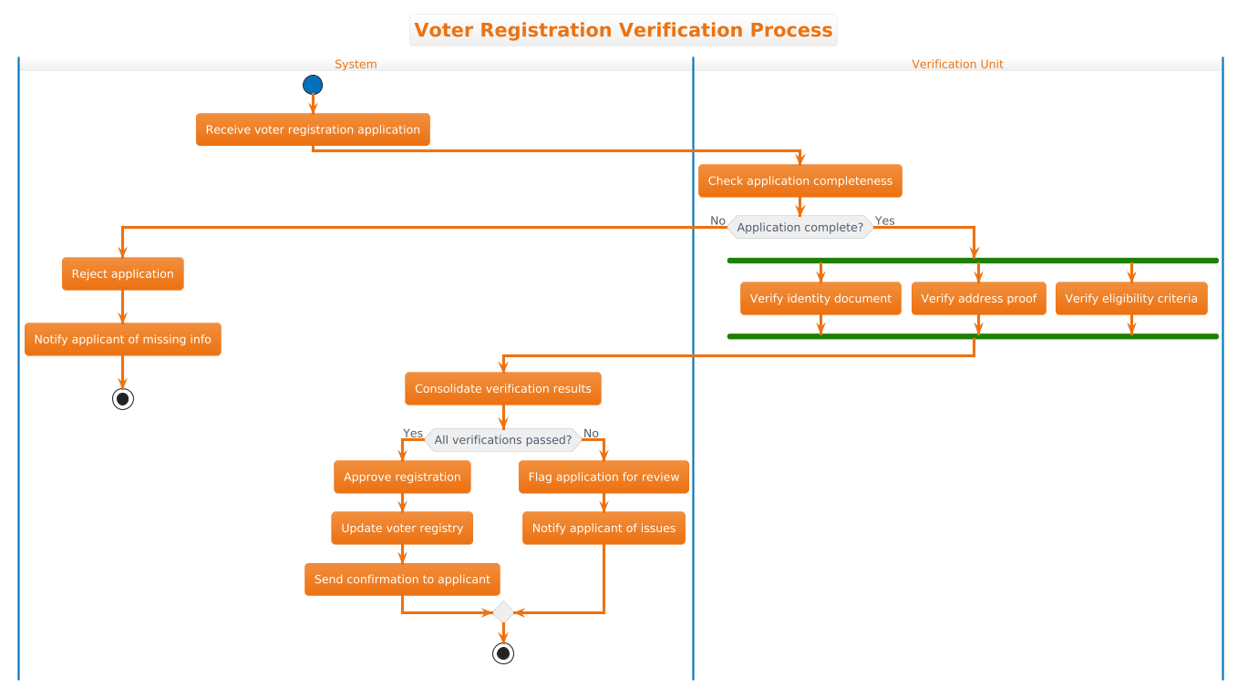
- Swimlanes: Separating responsibilities between the System (automated backend) and the Verification Unit (human or specialized service agents).
- Parallelism: Showing that certain checks (identity, address, eligibility) can happen simultaneously to optimize throughput.
- Decision Logic: Mapping the “if/else” paths that determine whether an application is approved, flagged, or rejected.
Target Domain Scope & Scenario
This model covers the core verification loop of a voter registration system. It intentionally excludes peripheral systems like payment processing or public notification services to focus strictly on the integrity of the verification decision. The diagram captures the critical juncture where raw data transitions into a verified citizen record.
Key Takeaways & Educational Insights
By building this model, you will learn how to:
- Use swimlanes to enforce separation of concerns between automated and manual processes.
- Implement fork/join patterns to represent parallel verification tasks.
- Structure conditional branching to handle both successful and failed verification scenarios cleanly.
Complete Diagram & Full Source Code
Below is the finished blueprint for the Voter Registration Verification Process. You can view the rendered diagram below, and then review the complete source code that generates it.
@startuml
!theme aws-orange
title Voter Registration Verification Process

|System|
start
:Receive voter registration application;

|Verification Unit|
:Check application completeness;

if (Application complete?) then (No)
  |System|
  :Reject application;
  :Notify applicant of missing info;
  stop
else (Yes)
  |Verification Unit|
  fork
    :Verify identity document;
  fork again
    :Verify address proof;
  fork again
    :Verify eligibility criteria;
  end fork
  |System|
  :Consolidate verification results;
  if (All verifications passed?) then (Yes)
    :Approve registration;
    :Update voter registry;
    :Send confirmation to applicant;
  else (No)
    :Flag application for review;
    :Notify applicant of issues;
  endif
  stop
endif
@endumlStep-by-Step Architectural Walkthrough
Let’s break down how to construct this diagram in VPasCode, moving from basic layout to complex logic flows.
Phase 1: Canvas Configuration & Layout Directives
Every professional diagram starts with a theme and a title. We begin by setting the visual identity and the diagram’s scope.
!theme aws-orange
title Voter Registration Verification Process
The !theme aws-orange directive applies a professional color palette suitable for government dashboards. The title directive ensures the diagram is self-documenting when exported or shared.
Phase 2: Declaring Core Entities, Actors, and Boundaries
The first structural element of an activity diagram is the swimlane. Swimlanes divide the diagram vertically to show which actor or system component is responsible for each action. In this scenario, we have two distinct boundaries: the automated System and the human or specialized Verification Unit.
|System|
start
:Receive voter registration application;

|Verification Unit|
:Check application completeness;
Notice the |System| syntax. This creates a vertical lane. The start node marks the entry point of the workflow. The first action :Receive voter registration application; is placed in the System lane, indicating that the intake is automated.
Phase 3: Mapping Data Flows & Key Interactions
Now we introduce the first critical decision point. The system must determine if the application is complete before proceeding. This uses the standard if syntax.
if (Application complete?) then (No)
  |System|
  :Reject application;
  :Notify applicant of missing info;
  stop
else (Yes)
  |Verification Unit|
Here, we see a parallel flow switch. If the answer is No, the flow stays in the |System| lane to reject the application and stops. If the answer is Yes, the flow moves to the |Verification Unit| lane, signaling a handoff to the verification process.
Phase 4: Grouping, Annotations & Visual Polish
The most complex part of this workflow is the parallel verification. We need to run three checks simultaneously: Identity, Address, and Eligibility. In PlantUML, this is achieved using fork and fork again.
  fork
    :Verify identity document;
  fork again
    :Verify address proof;
  fork again
    :Verify eligibility criteria;
  end fork
The fork keyword splits the flow into multiple parallel threads. The end fork keyword acts as a barrier, ensuring all parallel threads complete before the flow continues. After the parallel checks, the flow returns to the |System| lane to consolidate results and make the final approval decision.
Syntax & Keyword Deep Dive
To master PlantUML activity diagrams in VPasCode, you must understand the specific keywords that drive logic and layout.
|Lane Name|: Creates a vertical swimlane. Essential for separating system responsibilities (e.g., automated vs. manual).start/stop: Define the entry and exit points of the workflow. Every valid activity diagram must have a single start node.if / else / endif: The standard conditional syntax. You can nest these to create complex decision trees.fork / fork again / end fork: Creates parallel branches.forkstarts the first branch,fork againadds subsequent branches, andend forkjoins them back into a single flow.:Action Name;: Defines a process step. The colon at the start and semicolon at the end are required syntax for activity nodes.!theme: Applies a predefined color scheme to the entire diagram for consistent branding.
Best Practices & Pitfalls to Avoid
When building activity diagrams for government or enterprise systems, maintain these standards to ensure clarity and maintainability.
- Keep Swimlanes Balanced: Avoid creating swimlanes that contain only one or two steps. If a lane is sparse, consider merging it with a related process to reduce visual noise.
- Limit Nesting Depth: While PlantUML supports deep nesting, diagrams with more than 3 levels of
if/elsebecome hard to read. Consider splitting complex flows into sub-activities if the logic becomes too dense. - Use Descriptive Labels: In government workflows, precision matters. Use labels like
Verify identity documentinstead of genericCheck IDto ensure the diagram remains clear to auditors and developers. - Ensure Single Entry/Exit: Always use
startandstopnodes. Avoid multiple entry points or orphaned paths that could confuse the process logic.
Try It Yourself with VPasCode
Start Building PlantUML Activity Diagrams Faster with VPasCode
Test, preview, and customize this Voter Registration workflow online in VPasCode without installing any tools or configuring environments.