


In the fast-paced world of modern retail logistics, efficiency is the currency of survival. A Distribution Center System (DCS) acts as the heartbeat of supply chain operations, orchestrating the movement of goods from storage to the customer’s doorstep. When order volumes spike during peak seasons, the margin for error shrinks to zero. Visualizing these complex, time-sensitive interactions is not just about documentation; it is a critical engineering step to identify bottlenecks, define exception handling, and ensure system reliability before a single line of production code is written.

Diagramming-as-code offers a superior alternative to drag-and-drop tools for these scenarios. By using PlantUML within VPasCode, architects can define the entire lifecycle of an order—from receipt to shipping—in a text-based format that is version-friendly, portable, and instantly renderable. This approach allows teams to focus on the logic of interactions rather than the aesthetics of drawing, ensuring that the sequence diagram accurately reflects the system’s behavioral architecture.
Understanding the Model: Purpose, Scope & Problem Framing
This tutorial focuses on a Sequence Diagram, a specific type of interaction diagram used in Unified Modeling Language (UML) to describe how objects or systems interact over time. Unlike static diagrams like Class or Entity Relationship Diagrams, sequence diagrams capture the dynamic behavior of a system. They are essential for modeling the flow of messages between participants, such as actors, software components, and hardware devices.
Diagram Abstraction & Representation: In this context, the sequence diagram models the runtime interactions within a retail Distribution Center. Each vertical line (lifeline) represents a system component or actor, such as the Order Management System (OMS) or an Automated Picking Robot. Horizontal arrows represent the messages or data packets exchanged between these components. Activation bars on the lifelines indicate periods where a component is actively processing a request.
Target Domain Scope & Scenario: The scope covers the end-to-end fulfillment workflow. It begins when a customer places an order and ends when the shipment is dispatched. The model intentionally includes the Warehouse Control System (WCS), which bridges the gap between high-level business logic and low-level physical execution. It also accounts for critical failure paths, such as stockouts or quality check failures, ensuring the system architecture is robust against real-world disruptions.
Key Takeaways & Educational Insights: By constructing this diagram, you will gain clarity on how data flows between the OMS and the physical warehouse layers. You will learn how to represent conditional logic (e.g., “if stock is available”) using combined fragments, and how to manage lifeline activations to visualize processing overhead. This model serves as a blueprint for backend developers, QA engineers, and operations managers to align on process expectations.
Complete Diagram & Full Source Code
Before diving into the construction steps, review the complete model to understand the final output. This diagram utilizes the cerulean theme for a clean, professional look and includes detailed comments to explain the workflow logic.
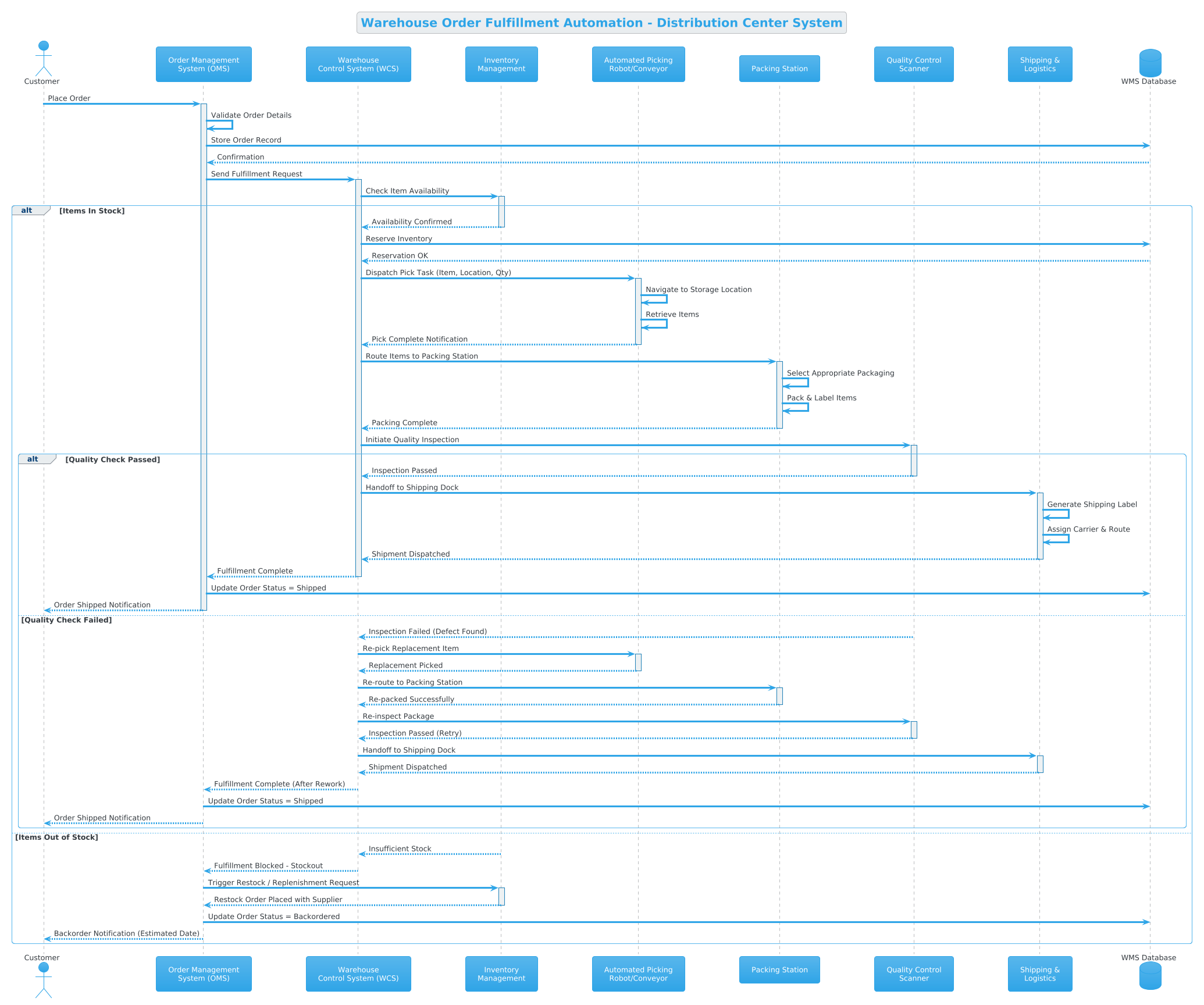
Copy the following source code to replicate this diagram. This is the full, ready-to-use PlantUML code that you can paste directly into the VPasCode editor.
@startuml

!theme cerulean

title Warehouse Order Fulfillment Automation - Distribution Center System

/'
  This sequence diagram illustrates the automated order fulfillment process
  within a Distribution Center System. It covers the end-to-end workflow from
  order receipt through picking, packing, quality check, and shipping dispatch.
  Alternative flows are included for out-of-stock items and failed quality checks,
  which trigger restocking or repicking respectively.
'/

actor Customer
participant "Order Management\nSystem (OMS)" as OMS
participant "Warehouse\nControl System (WCS)" as WCS
participant "Inventory\nManagement" as IMS
participant "Automated Picking\nRobot/Conveyor" as Picker
participant "Packing Station" as Packing
participant "Quality Control\nScanner" as QC
participant "Shipping &\nLogistics" as Shipping
database "WMS Database" as DB

Customer -> OMS : Place Order
activate OMS

OMS -> OMS : Validate Order Details
OMS -> DB : Store Order Record
DB --> OMS : Confirmation

OMS -> WCS : Send Fulfillment Request
activate WCS

WCS -> IMS : Check Item Availability
activate IMS

alt Items In Stock
    IMS --> WCS : Availability Confirmed
    deactivate IMS

    WCS -> DB : Reserve Inventory
    DB --> WCS : Reservation OK

    WCS -> Picker : Dispatch Pick Task (Item, Location, Qty)
    activate Picker

    Picker -> Picker : Navigate to Storage Location
    Picker -> Picker : Retrieve Items
    Picker --> WCS : Pick Complete Notification
    deactivate Picker

    WCS -> Packing : Route Items to Packing Station
    activate Packing

    Packing -> Packing : Select Appropriate Packaging
    Packing -> Packing : Pack & Label Items
    Packing --> WCS : Packing Complete
    deactivate Packing

    WCS -> QC : Initiate Quality Inspection
    activate QC

    alt Quality Check Passed
        QC --> WCS : Inspection Passed
        deactivate QC

        WCS -> Shipping : Handoff to Shipping Dock
        activate Shipping

        Shipping -> Shipping : Generate Shipping Label
        Shipping -> Shipping : Assign Carrier & Route
        Shipping --> WCS : Shipment Dispatched
        deactivate Shipping

        WCS --> OMS : Fulfillment Complete
        deactivate WCS

        OMS -> DB : Update Order Status = Shipped
        OMS --> Customer : Order Shipped Notification
        deactivate OMS

    else Quality Check Failed
        QC --> WCS : Inspection Failed (Defect Found)
        deactivate QC

        WCS -> Picker : Re-pick Replacement Item
        activate Picker
        Picker --> WCS : Replacement Picked
        deactivate Picker

        WCS -> Packing : Re-route to Packing Station
        activate Packing
        Packing --> WCS : Re-packed Successfully
        deactivate Packing

        WCS -> QC : Re-inspect Package
        activate QC
        QC --> WCS : Inspection Passed (Retry)
        deactivate QC

        WCS -> Shipping : Handoff to Shipping Dock
        activate Shipping
        Shipping --> WCS : Shipment Dispatched
        deactivate Shipping

        WCS --> OMS : Fulfillment Complete (After Rework)
        deactivate WCS

        OMS -> DB : Update Order Status = Shipped
        OMS --> Customer : Order Shipped Notification
        deactivate OMS
    end

else Items Out of Stock
    IMS --> WCS : Insufficient Stock
    deactivate IMS

    WCS --> OMS : Fulfillment Blocked – Stockout
    deactivate WCS

    OMS -> IMS : Trigger Restock / Replenishment Request
    activate IMS
    IMS --> OMS : Restock Order Placed with Supplier
    deactivate IMS

    OMS -> DB : Update Order Status = Backordered
    OMS --> Customer : Backorder Notification (Estimated Date)
    deactivate OMS
end

@endumlStep-by-Step Architectural Walkthrough
Building a complex sequence diagram requires a structured approach. We will break down the construction of this Warehouse Order Fulfillment diagram into four distinct phases, ensuring that every component and interaction is defined logically.
Phase 1: Canvas Configuration & Layout Directives
Every PlantUML diagram begins with setup directives that define the visual theme and structural metadata. In this example, we start with @startuml to signal the beginning of the code. We then apply the !theme cerulean directive, which overrides default styling to provide a modern, blue-toned aesthetic suitable for professional documentation.
Next, we define the title to give the diagram a clear identifier. Crucially, we add a comment block using /' at the start and '/ at the end. This multi-line comment is visible in the rendered diagram and serves as an embedded manual for anyone reading the model later.
!theme cerulean

title Warehouse Order Fulfillment Automation - Distribution Center System

/'
  This sequence diagram illustrates the automated order fulfillment process
  within a Distribution Center System.
'/
Phase 2: Declaring Core Entities, Actors, and Boundaries
Once the canvas is set, we declare the participants. In PlantUML, participants can be actors (human users), standard objects, or specific system types like databases. We use actor for the Customer and database for the WMS Database to provide semantic clarity.
For complex system components, we use the participant keyword. Note the use of the as keyword to assign short aliases (e.g., as OMS). This allows us to reference the long names in the diagram while keeping the interaction arrows concise and readable.
actor Customer
participant "Order Management\nSystem (OMS)" as OMS
participant "Warehouse\nControl System (WCS)" as WCS
database "WMS Database" as DB
Phase 3: Mapping Data Flows & Key Interactions
With participants defined, we map the chronological flow. Solid arrows (->) denote synchronous calls, while dashed arrows (-->) denote return messages. We use activate and deactivate to draw activation bars on lifelines, indicating when a component is busy processing.
For example, the Customer places an order, activating the OMS. The OMS then validates and stores the record in the database before passing control to the WCS. This step-by-step mapping ensures the temporal sequence is preserved.
Customer -> OMS : Place Order
activate OMS

OMS -> OMS : Validate Order Details
OMS -> DB : Store Order Record
DB --> OMS : Confirmation
Phase 4: Grouping, Annotations & Visual Polish
Real-world systems rarely follow a single linear path. We use the alt (alternative) combined fragment to model conditional logic, such as checking if items are in stock. Inside the alt block, we define the primary path and the else path for exceptions.
This structure allows us to nest logic. For instance, inside the “Items In Stock” block, we have another alt block for the Quality Check. This nesting accurately reflects the decision trees within the warehouse automation logic.
alt Items In Stock
    IMS --> WCS : Availability Confirmed
    deactivate IMS
else Items Out of Stock
    IMS --> WCS : Insufficient Stock
    deactivate IMS
end
Syntax & Keyword Deep Dive
To master diagram-as-code, you must understand the specific syntax keywords used in PlantUML. Here is a breakdown of the critical elements utilized in this warehouse fulfillment model.
actor: Defines a human or external entity interacting with the system, such as theCustomer.participant: Represents a system component, software service, or physical station like thePacking Station.database: Specifically denotes a data storage entity, distinguishing it from processing logic.->(Arrow): Indicates a synchronous message or method call. The sender waits for a response.-->(Dashed Arrow): Indicates a return message or asynchronous response.activate/deactivate: Controls the visibility of the activation rectangle on a lifeline, showing when a participant is processing.alt/else/end: Keywords for Combined Fragments.altstarts an alternative block,elsedefines the fallback condition, andendcloses the block.!theme: A directive to apply a specific visual style to the entire diagram.
Best Practices & Pitfalls to Avoid
Creating maintainable diagrams requires discipline. Follow these best practices to ensure your PlantUML models remain clear and useful over time.
- Keep Lifelines Active Only When Needed: Do not activate a participant for the entire duration of the diagram. Use
deactivateimmediately after processing to avoid clutter and accurately represent idle time. - Use Descriptive Message Labels: Avoid generic labels like “Process Data.” Instead, use specific terms like “Dispatch Pick Task (Item, Location, Qty)” to provide context.
- Manage Nested Logic: While nesting
altblocks is powerful, avoid going deeper than two or three levels. If the logic becomes too complex, consider splitting the diagram into multiple views. - Consistent Naming Conventions: Always use the
askeyword to define short aliases for long participant names. This keeps the interaction arrows clean and readable.
Try It Yourself with VPasCode
Start Building PlantUML Sequence Diagrams Faster with VPasCode
Instantly render and customize your warehouse automation workflows online without installing any tools or configuring local environments.