


When designing software systems, communicating high-level boundaries clearly to both technical and non-technical stakeholders is essential. In this masterclass tutorial, we will walk through how to build a professional C4 System Context diagram from scratch using PlantUML inside the free VPasCode editor.
Why Use a Diagram-as-Code Approach for C4 Models?
Traditional drag-and-drop drawing tools often lead to misaligned boxes, inconsistent styling, and tedious manual updates whenever architecture evolves. By leveraging a diagram-as-code tool like a free PlantUML editor, your documentation stays synchronized with code, version-controlled, and clean. Using VPasCode, you get real-time rendering and automatic format detection that makes visualizing software architecture effortless.
The Masterclass Case Study: Online Grocery Store Architecture
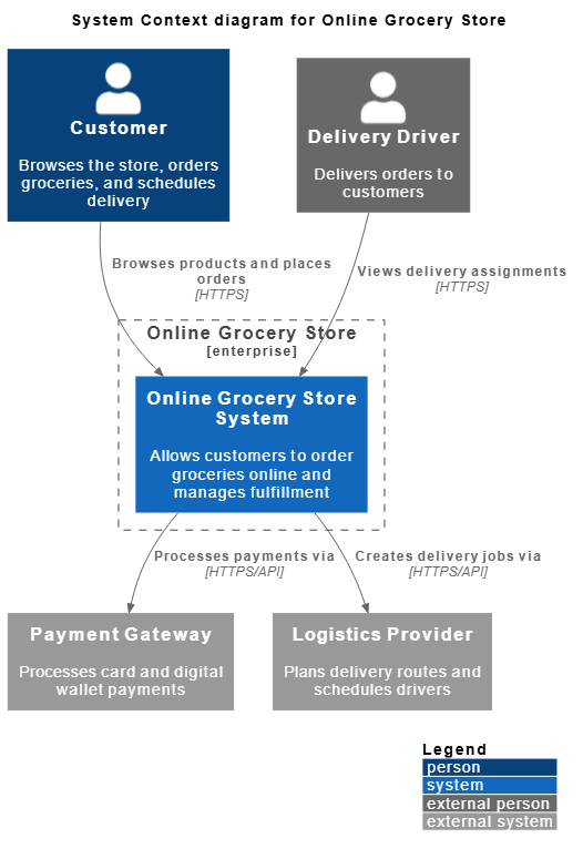
To demonstrate how to structure a robust system context diagram, let us look at an Online Grocery Store platform. This architecture needs to capture end-users, external delivery drivers, the core grocery system, and third-party services like payment gateways and logistics providers.
Here is the complete PlantUML source code we will break down step-by-step:
@startuml
!include https://raw.githubusercontent.com/plantuml-stdlib/C4-PlantUML/master/C4_Context.puml
skinparam vpDiagramType C4modelSystemContextDiagram

LAYOUT_TOP_DOWN()
LAYOUT_WITH_LEGEND()

title System Context diagram for Online Grocery Store

Person(customer, "Customer", "Browses the store, orders groceries, and schedules delivery")
Person_Ext(driver, "Delivery Driver", "Delivers orders to customers")

Enterprise_Boundary(grocery_co, "Online Grocery Store") {
  System(grocery_system, "Online Grocery Store System", "Allows customers to order groceries online and manages fulfillment")
}

System_Ext(payment, "Payment Gateway", "Processes card and digital wallet payments")
System_Ext(shipping, "Logistics Provider", "Plans delivery routes and schedules drivers")

Rel(customer, grocery_system, "Browses products and places orders", "HTTPS")
Rel(grocery_system, payment, "Processes payments via", "HTTPS/API")
Rel(grocery_system, shipping, "Creates delivery jobs via", "HTTPS/API")
Rel(driver, grocery_system, "Views delivery assignments", "HTTPS")

@enduml
Step-by-Step Walkthrough of the Code
1. Setting Up the Foundational Environment
I start by initializing the script with standard PlantUML tags and importing the official C4-PlantUML standard library macros. By referencing C4_Context.puml, we unlock semantic elements tailored specifically for system context diagrams.
- Library Inclusion:
!include .../C4_Context.pumlloads standard shapes, colors, and styling rules for people, systems, and boundaries. - Diagram Typing & Layout: Setting
skinparam vpDiagramType C4modelSystemContextDiagramensures proper integration within VPasCode, whileLAYOUT_TOP_DOWN()organizes the visual hierarchy cleanly from top to bottom. I also enableLAYOUT_WITH_LEGEND()to automatically generate a helpful reference guide at the bottom right of the canvas.
2. Defining Actors and Users
Next, I need to define the human actors interacting with our ecosystem. I differentiate between standard system users and external entities using specific C4 macros:
- The Core User: I create a primary user using
Person(customer, "Customer", ...)who initiates orders and browses inventory. - The External Actor: I define a delivery driver using
Person_Ext(driver, "Delivery Driver", ...)to highlight that while they interact with our fulfillment flow, they exist outside our core internal security perimeter.
3. Establishing Organizational Boundaries and Core Systems
Architectural clarity requires clear boundaries. To encapsulate what our company owns versus what relies on external vendors, I establish an enterprise boundary:
- Enterprise Boundary: Using
Enterprise_Boundary(grocery_co, "Online Grocery Store")creates a dashed container box visually grouping internal infrastructure. - Internal System: Inside this boundary, I place our main software asset using
System(grocery_system, "Online Grocery Store System", ...).
4. Integrating External Systems
No modern e-commerce platform operates in isolation. I define external dependencies outside the enterprise boundary using specialized external system macros:
- Payment Processing:
System_Ext(payment, "Payment Gateway", ...)represents third-party financial transactions. - Logistics & Shipping:
System_Ext(shipping, "Logistics Provider", ...)handles route planning and driver assignment.
5. Mapping Relationships and Protocols
To tie the architecture together, I map out directional interactions and communication protocols using the Rel() macro:
- Customer Flow:
Rel(customer, grocery_system, "Browses products and places orders", "HTTPS")illustrates how users connect securely to the core platform. - Backend Integrations: I map backend dependencies like payment processing and shipping providers with explicit protocol labels (
"HTTPS/API") to give engineers immediate technical context.
Conclusion & Try It Yourself
Building clean software architecture diagrams does not require cumbersome desktop tools or complex file configurations. By combining PlantUML’s powerful C4 syntax with VPasCode, you can write, render, and share architecture diagrams in seconds.
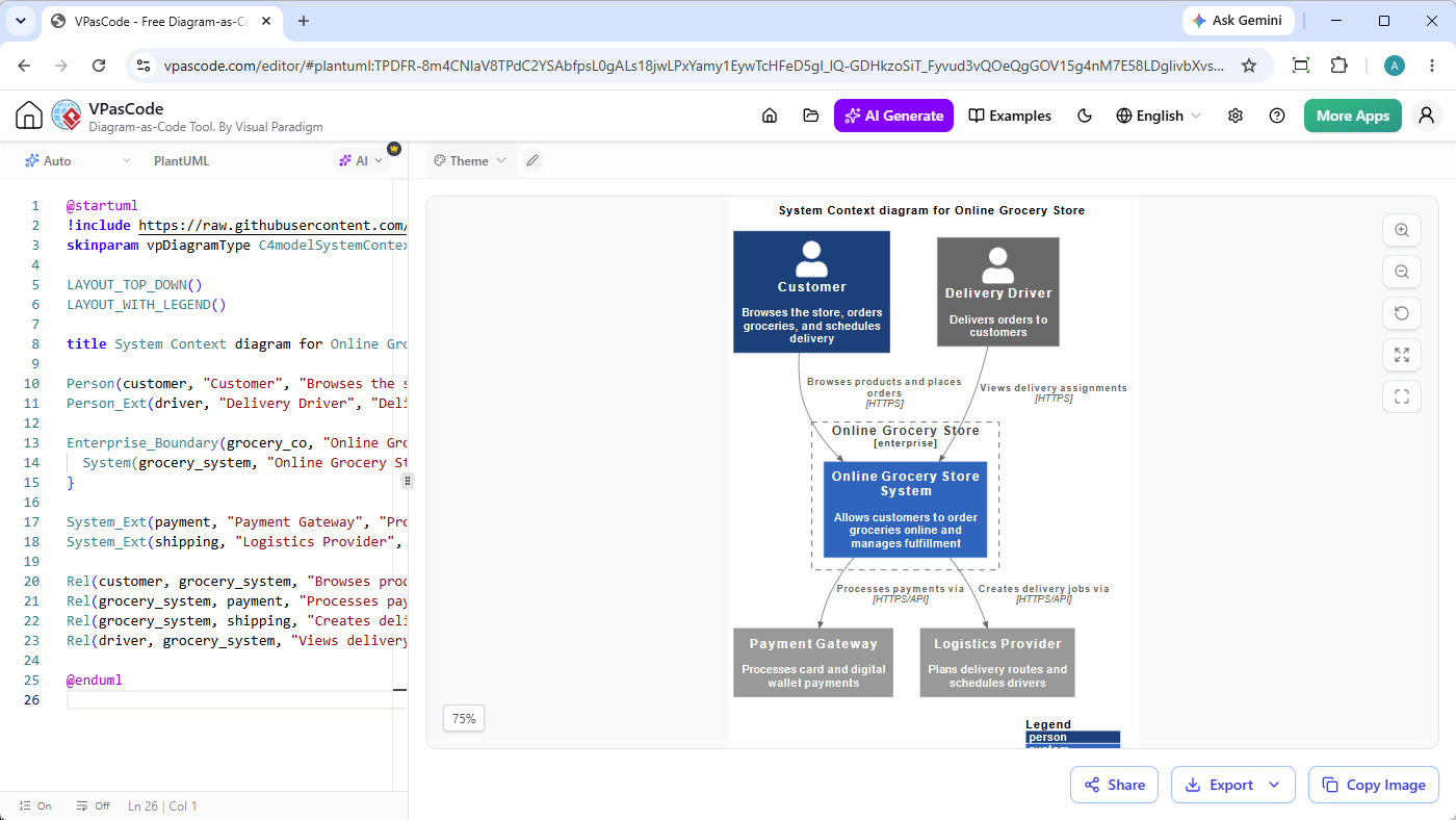
Ready to try building your own system architecture? Head over to the free VPasCode online editor, paste this code snippet, and watch your diagram render in real time!