


In the high-stakes world of online gaming, the matchmaking system is the backbone of player retention. When millions of players connect simultaneously, the architecture must handle complex logic: balancing skill levels, minimizing latency based on region, and ensuring game mode compatibility. Without a clear visual model, these workflows become opaque, leading to bugs, unfair matches, and frustrated users.
Activity diagrams are the ideal tool for mapping these asynchronous, multi-party interactions. By using VPasCode, our free PlantUML editor, developers can rapidly prototype and visualize the flow of a multiplayer game lobby. This approach transforms abstract requirements into a concrete, living document that architects and engineers can review in real-time.
This tutorial demonstrates how to construct a professional-grade activity diagram for a Multiplayer Game Matchmaking Server. We will utilize swimlanes to separate concerns between the Player, Lobby Service, and Matchmaking Engine, while leveraging PlantUML’s powerful flow control features like split, if/else, and repeat loops to model real-world conditional logic.
Understanding the Model: Purpose, Scope & Problem Framing
Diagram Abstraction & Representation
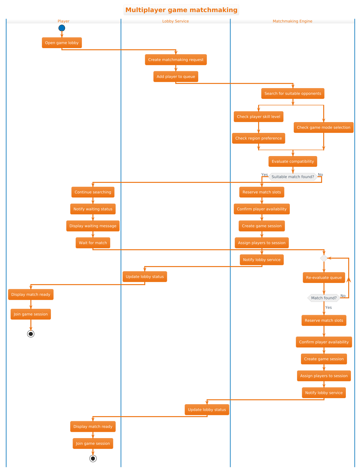
An activity diagram models the dynamic behavior of a system over time. Unlike a class diagram which shows static structure, this diagram captures the process of finding a match. It answers critical questions: What happens when a player joins? How does the system decide if a match exists? What happens if no match is available?
By using swimlanes, we assign responsibility to specific components:
- Player: The initiator of the action and the recipient of the final state.
- Lobby Service: The coordinator that manages the queue and communicates status.
- Matchmaking Engine: The core logic processor that evaluates compatibility.
Target Domain Scope & Scenario
This model focuses specifically on the matchmaking phase of the game lifecycle. It excludes user authentication, character selection, or in-game combat. The boundary is drawn from the moment a player opens the lobby until they are either placed in a game session or the search times out.
Key Takeaways & Educational Insights
By following this tutorial, you will learn how to:
- Structure complex workflows using PlantUML swimlanes to clarify ownership.
- Implement parallel processing using the
splitdirective to model concurrent checks (skill, region, mode). - Handle conditional logic and loops to represent retry mechanisms when matches are not immediately found.
Complete Diagram & Full Source Code
Below is the finished blueprint for the Multiplayer Game Matchmaking activity diagram. This diagram uses the aws-orange theme for a clean, professional look.
@startuml
!theme aws-orange
title Multiplayer game matchmaking

|Player|
start
:Open game lobby;

|Lobby Service|
:Create matchmaking request;
:Add player to queue;

|Matchmaking Engine|
:Search for suitable opponents;
split
    :Check player skill level;
    :Check region preference;
split again
    :Check game mode selection;
endsplit
:Evaluate compatibility;

if (Suitable match found?) then (Yes)
    :Reserve match slots;
    :Confirm player availability;
    :Create game session;
    :Assign players to session;
    :Notify lobby service;
    |Lobby Service|
    :Update lobby status;
    |Player|
    :Display match ready;
    :Join game session;
    stop
else (No)
    :Continue searching;
    :Notify waiting status;
    |Player|
    :Display waiting message;
    :Wait for match;
    |Matchmaking Engine|
    repeat
        :Re-evaluate queue;
    repeat while (Match found?) is (No)
    ->Yes;
    :Reserve match slots;
    :Confirm player availability;
    :Create game session;
    :Assign players to session;
    :Notify lobby service;
    |Lobby Service|
    :Update lobby status;
    |Player|
    :Display match ready;
    :Join game session;
    stop
endif

@endumlStep-by-Step Architectural Walkthrough
Phase 1: Canvas Configuration & Layout Directives
Every PlantUML diagram begins with initialization directives. We start by setting the theme to aws-orange for consistent branding. We also define the title, which appears at the top of the rendered diagram. This ensures the diagram is self-documenting.
!theme aws-orange
title Multiplayer game matchmaking
Next, we declare the swimlanes. PlantUML uses the pipe symbol | to define a new lane. This immediately separates the diagram into three vertical sections, representing the distinct system components involved in the process.
|Player|
|Lobby Service|
|Matchmaking Engine|
Phase 2: Declaring Core Entities, Actors, and Boundaries
The diagram starts with the Player action. In activity diagrams, start marks the entry point. The first action is Open game lobby. We then move to the Lobby Service lane to handle the backend logic. This service creates the request and adds the player to a waiting queue.
start
:Open game lobby;
:Create matchmaking request;
:Add player to queue;
This phase establishes the initial state and the handoff between the client (Player) and the server infrastructure (Lobby Service).
Phase 3: Mapping Data Flows & Key Interactions
The core complexity lies in the Matchmaking Engine logic. We need to check multiple criteria simultaneously. PlantUML’s split directive allows us to draw parallel flows that happen concurrently.
split
    :Check player skill level;
    :Check region preference;
split again
    :Check game mode selection;
endsplit
:Evaluate compatibility;
After the parallel checks, the flow converges to Evaluate compatibility. From here, we introduce a decision point using the if directive. This determines whether the system proceeds to the success path or enters a retry loop.
if (Suitable match found?) then (Yes)
    ...
else (No)
    ...
endif
Phase 4: Grouping, Annotations & Visual Polish
The else branch handles the scenario where no match is immediately available. We use the repeat directive to model a polling loop. The engine re-evaluates the queue until a match is found or a timeout occurs (implicit in the loop condition).
repeat
    :Re-evaluate queue;
repeat while (Match found?) is (No)
    ->Yes;
This loop ensures the system keeps searching without blocking indefinitely. Finally, we converge back to the success path: reserving slots, creating the session, and notifying the player to join.
Syntax & Keyword Deep Dive
To build diagrams like this in VPasCode, understanding the specific PlantUML syntax is essential. Here are the key keywords used in this tutorial:
title: Sets the header text for the diagram. Use this for clear identification.!theme: Applies a predefined color scheme (e.g.,aws-orange) to the entire diagram instantly.|Lane Name|: Defines a swimlane. Actions following this tag belong to that lane until a new tag is encountered.split/split again/endsplit: Creates parallel branches of execution. All branches inside a split block execute simultaneously before converging at theendsplit.if/then/else: Implements conditional logic. The flow splits based on a boolean condition.repeat/while: Creates a loop. The diagram will iterate until the condition is met.start/stop: Marks the beginning and end points of the activity flow.
Best Practices & Pitfalls to Avoid
When creating activity diagrams for complex systems like matchmaking, keep these principles in mind:
- Keep Swimlanes Balanced: Ensure each lane has a logical amount of responsibility. If one lane is too crowded, consider splitting it into sub-processes.
- Use Clear Labels: Avoid vague terms like “Process Data.” Use specific verbs like “Validate Player Skill” or “Reserve Match Slots.”
- Limit Parallel Complexity: While
splitis powerful, too many parallel branches can make the diagram unreadable. Group related checks together. - Consistent Endpoints: Ensure all paths eventually lead to a
stopnode. Dead ends confuse readers about the system’s final state.
Start Building PlantUML Activity Diagrams Faster with VPasCode
Instantly prototype, preview, and customize your multiplayer game architecture diagrams online in VPasCode without installing any tools.