


In the complex world of logistics and supply chain management, clarity is currency. When a customer initiates a freight booking, multiple backend systems must synchronize to validate capacity, check pricing, and reserve warehouse space. Without a clear visual model, these interactions can lead to race conditions, data inconsistencies, and poor user experiences.

This tutorial guides you through building a professional sequence diagram that models the Freight Booking Confirmation scenario. Using PlantUML within the VPasCode free web editor, you will learn how to define actors, participants, and the intricate logical flows (including alternative paths for capacity issues) that drive a modern Freight Forwarding System. By mastering this diagram-as-code approach, you create living documentation that evolves with your architecture.
Understanding the Model: Purpose, Scope & Problem Framing
Before writing a single line of code, it is essential to understand the abstraction and the specific problem this diagram solves.
Diagram Abstraction & Representation
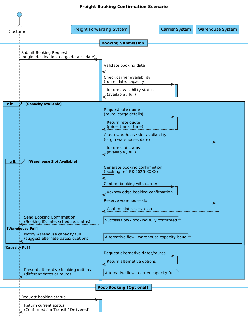
A sequence diagram is the ideal tool for modeling time-ordered interactions between system components. In this context, it answers the question: “What happens, in what order, and under what conditions, when a customer requests a freight booking?”
- Lifelines: Represent the distinct entities involved (Customer, Freight Forwarding System, Carrier System, Warehouse System).
- Messages: Represent the data exchange (requests, quotes, confirmations) flowing between these entities.
- Activation Bars: Indicate when a participant is actively processing a request.
- Combined Fragments: The
altblocks allow us to model decision logic, such as checking if a carrier has capacity before proceeding.
Target Domain Scope & Scenario
This diagram focuses strictly on the Booking Confirmation phase of the logistics workflow. It intentionally excludes:
- Post-booking tracking (unless requested as a separate optional flow).
- Payment processing details (though pricing is validated).
- Physical movement of goods.
The scope is defined by the interaction boundaries between the Customer and the backend orchestration logic, extending to external dependencies like the Carrier System and Warehouse System.
Key Takeaways & Educational Insights
By completing this tutorial, you will gain:
- Architectural Clarity: A precise map of how the Freight Forwarding System orchestrates external services.
- Logic Visualization: How to visually represent conditional flows (e.g., “If carrier is full, request alternatives”) using PlantUML syntax.
- Documentation Standards: How to use themes, notes, and clear naming conventions to make diagrams readable for stakeholders.
Complete Diagram & Full Source Code
Below is the complete blueprint for the Freight Booking Confirmation sequence diagram. You can view the rendered result immediately in the VPasCode editor.
@startuml
!include https://static.visual-paradigm.com/web/resources/plantuml-stdlib/themes/vp.puml

title Freight Booking Confirmation Scenario

/'
This sequence diagram illustrates the freight booking confirmation process in a Freight Forwarding System.
It covers the interaction between the Customer, Freight Forwarding System, Carrier System, and Warehouse System.
Alternative flows are represented for successful confirmation, capacity issues, and pricing validation failures.
'/

actor "Customer" as C
participant "Freight Forwarding System" as FFS
participant "Carrier System" as CS
participant "Warehouse System" as WS

== Booking Submission ==
C -> FFS: Submit Booking Request\n(origin, destination, cargo details, date)
activate FFS

FFS -> FFS: Validate booking data
FFS -> CS: Check carrier availability\n(route, date, capacity)
activate CS

CS --> FFS: Return availability status\n(available / full)
deactivate CS

alt Capacity Available
    FFS -> CS: Request rate quote\n(route, cargo details)
    activate CS
    CS --> FFS: Return rate quote\n(price, transit time)
    deactivate CS

    FFS -> WS: Check warehouse slot availability\n(origin warehouse, date)
    activate WS
    WS --> FFS: Return slot status\n(available / full)
    deactivate WS

    alt Warehouse Slot Available
        FFS -> FFS: Generate booking confirmation\n(booking ref: BK-2026-XXXX)

        FFS -> CS: Confirm booking with carrier
        activate CS
        CS --> FFS: Acknowledge booking confirmation
        deactivate CS

        FFS -> WS: Reserve warehouse slot
        activate WS
        WS --> FFS: Confirm slot reservation
        deactivate WS

        FFS --> C: Send Booking Confirmation\n(Booking ID, rate, schedule, status)
        note right: Success flow - booking fully confirmed

    else Warehouse Full
        FFS --> C: Notify warehouse capacity full\n(suggest alternate dates/locations)
        note right: Alternative flow - warehouse capacity issue
    end

else Capacity Full
    FFS -> CS: Request alternative dates/routes
    activate CS
    CS --> FFS: Return alternative options
    deactivate CS

    FFS --> C: Present alternative booking options\n(different dates or routes)
    note right: Alternative flow - carrier capacity full
end

deactivate FFS

== Post-Booking (Optional) ==
C -> FFS: Request booking status
activate FFS
FFS --> C: Return current status\n(Confirmed / In-Transit / Delivered)
deactivate FFS
@endumlStep-by-Step Architectural Walkthrough
Now, let’s deconstruct the code to understand how we built this diagram from scratch using VPasCode.
Phase 1: Canvas Configuration & Layout Directives
Every professional PlantUML diagram starts with setup directives. We begin by including the Visual Paradigm theme to ensure the diagram looks polished and consistent with modern UI standards.
!include https://static.visual-paradigm.com/web/resources/plantuml-stdlib/themes/vp.puml

title Freight Booking Confirmation Scenario

/'
This sequence diagram illustrates the freight booking confirmation process in a Freight Forwarding System.
... (comment block)
'/
Key Actions:
!include ...: Loads the external theme file for styling.title: Sets the official name of the diagram./' ... '/: Creates a multi-line comment block. This is excellent for documentation, explaining the scope of the diagram directly within the code file.
Phase 2: Declaring Core Entities, Actors, and Boundaries
Next, we define the participants in our scenario. In sequence diagrams, these are represented as vertical lifelines.
actor "Customer" as C
participant "Freight Forwarding System" as FFS
participant "Carrier System" as CS
participant "Warehouse System" as WS
Key Actions:
actor: Used for the external human user (Customer).participant: Used for internal systems or services (FFS, CS, WS).as [Alias]: We assign short aliases (C, FFS, CS, WS) to make the message arrows easier to read and write later.
Phase 3: Mapping Data Flows & Key Interactions
This phase constructs the chronological flow of the booking process. We use arrows to represent messages and activation bars to show processing time.
== Booking Submission ==
C -> FFS: Submit Booking Request\n(origin, destination, cargo details, date)
activate FFS

FFS -> FFS: Validate booking data
FFS -> CS: Check carrier availability\n(route, date, capacity)
activate CS
Key Actions:
->: Represents a synchronous message (the sender waits for a response).-->: Represents an asynchronous message (the sender does not wait).activate/deactivate: Visually draws the “activation bar” on the lifeline to indicate when a component is busy.== Section ==: Divides the diagram into logical headers for readability.
Phase 4: Grouping, Annotations & Visual Polish
The most complex part of this diagram is handling the logic. We use combined fragments to represent the alt (alternative) flows.
alt Capacity Available
    ... (inner logic)
else Warehouse Full
    ... (alternative logic)
end
Key Actions:
alt ... else ... end: This block creates a conditional branching path. It models scenarios where the system must make a decision (e.g., Is the carrier full?).note right: Adds a sticky note to explain the outcome of a specific path (e.g., “Success flow” vs. “Warehouse capacity issue”).
Syntax & Keyword Deep Dive
To master PlantUML, you need to understand the specific keywords that control the diagram’s behavior.
actor: Defines a human user or external role interacting with the system.participant: Defines a system, service, or database component.->(Solid Arrow): Synchronous call. The sender waits for the receiver to process the request before continuing.-->(Dashed Arrow): Asynchronous response or non-blocking call.alt/else/end: Constructs a combined fragment.altstarts an alternative block,elsedefines a fallback condition, andendcloses the block.activate/deactivate: Explicitly controls the vertical activation bar on a lifeline, showing when a component is processing.\n: The newline escape character used within message labels to wrap text (e.g.,Request\nDetails).note right: Places a note box to the right of the specified participant or message.
Best Practices & Pitfalls to Avoid
When building sequence diagrams for logistics and enterprise systems, keep these guidelines in mind:
- Keep Lifelines Logical: Avoid creating too many participants. Group related systems (e.g., “Carrier System”) rather than splitting them into individual microservices unless the interaction is critical.
- Use Clear Aliases: Always use
as [Alias]for long participant names. It makes the message arrows (e.g.,FFS -> CS) much cleaner than writing full names repeatedly. - Document the Alternatives: In logistics, failures are common. Use
altblocks to explicitly show what happens when capacity is full or validation fails. This prevents “happy path” only documentation. - Use Themes: Always include a theme (like
vp.puml) to ensure your diagrams look professional and consistent with your brand identity without manual CSS tweaking.
Try It Yourself with VPasCode
Start Building PlantUML Sequence Diagrams Faster with VPasCode
Instantly render, customize, and share your logistics workflow diagrams online with zero installation required.