


In the rapidly evolving landscape of digital health, the Telemedicine Portal serves as the central nervous system for remote healthcare delivery. As healthcare providers transition from traditional in-person visits to virtual care models, the need for clear, standardized system boundaries becomes critical. A well-structured architecture ensures that patient data flows securely between doctors, patients, and external support systems like pharmacies and payment gateways.

Visual modeling plays a pivotal role in this transition. By using a Use Case Diagram, architects can define the functional scope of the portal without getting bogged down in implementation details. This tutorial leverages VPasCode, the free web-based PlantUML editor, to demonstrate how to construct a professional-grade Telemedicine Portal diagram. Diagram-as-code allows you to maintain living documentation that evolves with your system, ensuring that requirements are always visible and up-to-date.
Understanding the Model: Purpose, Scope & Problem Framing
Diagram Abstraction & Representation
A Use Case Diagram is the ideal tool for high-level requirement analysis. In this context, it models the functional goals of the system rather than the internal logic. The diagram distinguishes between Actors (users or external systems interacting with the portal) and Use Cases (the specific actions or services provided by the system). By separating these concerns, stakeholders can quickly understand who can do what within the healthcare ecosystem.
Target Domain Scope & Scenario
This diagram focuses specifically on the Telemedicine Portal boundary. It intentionally excludes external system internals (like the internal database schema of the payment gateway) and focuses on the interactions at the system edge. The scope covers three primary domains:
- Patient Experience: Registration, scheduling, and virtual consultations.
- Provider Workflows: Managing prescriptions, reviewing patient history, and setting availability.
- System Integration: Interactions with secondary actors like pharmacy systems and notification services.
Key Takeaways & Educational Insights
By building this model, you will gain clarity on system boundaries and actor responsibilities. You will learn how to represent external dependencies (like payment gateways) as secondary actors, ensuring your architecture reflects real-world integrations. This clarity is essential for compliance and security audits in the healthcare industry.
Complete Diagram & Full Source Code
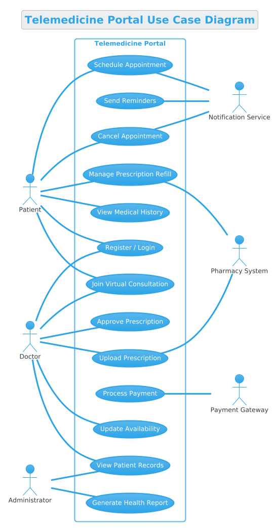
Below is the complete blueprint for the Telemedicine Portal Use Case Diagram. You can view the rendered output and edit the code directly in the VPasCode web editor.
@startuml
!theme cerulean

title Telemedicine Portal Use Case Diagram

/'
This use case diagram models the functional scope of a Telemedicine Portal.
The system facilitates remote healthcare delivery, enabling patients to consult with doctors virtually.
Primary actors (patients and doctors) interact with the system to manage appointments, conduct consultations, and access health records.
Secondary actors (payment gateway, pharmacy system, and notification service) support core functions like processing payments, fulfilling prescriptions, and sending alerts.
The diagram captures key workflows such as scheduling, virtual visits, prescription management, and administrative oversight.
'/

left to right direction

rectangle "Telemedicine Portal" {
  usecase "Register / Login" as UC1
  usecase "Schedule Appointment" as UC2
  usecase "Cancel Appointment" as UC3
  usecase "Join Virtual Consultation" as UC4
  usecase "View Medical History" as UC5
  usecase "Upload Prescription" as UC6
  usecase "Manage Prescription Refill" as UC7
  usecase "Process Payment" as UC8
  usecase "Send Reminders" as UC9
  usecase "Generate Health Report" as UC10
  usecase "Update Availability" as UC11
  usecase "View Patient Records" as UC12
  usecase "Approve Prescription" as UC13
}

' Primary actors (left side)
actor "Patient" as P
actor "Doctor" as D
actor "Administrator" as A

' Secondary actors (right side)
actor "Payment Gateway" as PG
actor "Pharmacy System" as Pharm
actor "Notification Service" as NS

' Patient use cases
P -- UC1
P -- UC2
P -- UC3
P -- UC4
P -- UC5
P -- UC7

' Doctor use cases
D -- UC1
D -- UC4
D -- UC6
D -- UC11
D -- UC12
D -- UC13

' Administrator use cases
A -- UC10
A -- UC12

' Secondary actor associations
UC8 -- PG
UC7 -- Pharm
UC6 -- Pharm
UC9 -- NS
UC2 -- NS
UC3 -- NS

@endumlStep-by-Step Architectural Walkthrough
Phase 1: Canvas Configuration & Layout Directives
Before defining actors, we must configure the canvas to ensure the diagram renders correctly. We start by setting the theme and direction. The !theme cerulean directive applies a clean, professional color palette suitable for medical documentation. The left to right direction ensures that primary actors appear on the left and secondary actors on the right, creating a natural reading flow.
!theme cerulean
left to right direction
Phase 2: Declaring Core Entities, Actors, and Boundaries
Next, we define the system boundary using a rectangle. This encapsulates all internal use cases. We then declare the primary actors (Patient, Doctor, Administrator) and secondary actors (Payment Gateway, Pharmacy, Notification). Naming these clearly helps stakeholders map the diagram to real-world roles.
rectangle "Telemedicine Portal" {
  usecase "Register / Login" as UC1
  ...
}
actor "Patient" as P
actor "Doctor" as D
actor "Administrator" as A
Phase 3: Mapping Data Flows & Key Interactions
The core of the diagram lies in the associations. We use the -- operator to link actors to use cases. For example, the Patient actor is connected to Schedule Appointment and Join Virtual Consultation. This visualizes the user journey without implying implementation details.
P -- UC2
P -- UC4
D -- UC6
D -- UC13
Phase 4: Grouping, Annotations & Visual Polish
Finally, we add secondary actor associations. These represent external dependencies. For instance, Process Payment connects to the Payment Gateway. We also include a title and a comment block (/' ... '/) to provide context for anyone reading the diagram later. This ensures the diagram remains self-documenting.
title Telemedicine Portal Use Case Diagram
/'
This use case diagram models the functional scope...
'/
Syntax & Keyword Deep Dive
To master PlantUML in VPasCode, understanding the specific syntax keywords is essential. Here is a breakdown of the core elements used in this Telemedicine diagram:
@startuml: Marks the beginning of the diagram definition. Every PlantUML script must start with this tag.!theme cerulean: A directive that applies a specific CSS theme to the rendered diagram for visual consistency.title: Sets the main heading displayed above the diagram.rectangle: Defines the system boundary, grouping all internal use cases within a box.usecase: Declares a specific functional goal or service provided by the system.actor: Represents a user or external system interacting with the boundary.--: The association operator. It creates a line connecting an actor to a use case without an arrowhead, indicating a relationship./' ... '/: A comment block syntax. Text inside is rendered as a description or context note but is not part of the logic.
Best Practices & Pitfalls to Avoid
When modeling complex healthcare systems, adhere to these best practices to maintain clarity:
- Keep Boundaries Tight: Only include use cases that fall within the Telemedicine Portal. Do not model the internal logic of the Pharmacy System; treat it as a secondary actor.
- Consistent Naming: Use clear, action-oriented names for use cases (e.g., “Upload Prescription” instead of “Prescription”).
- Avoid Over-Clutter: If a diagram becomes too dense, consider splitting it into sub-diagrams (e.g., one for Patient, one for Doctor).
- Use Comments for Context: Always include a comment block explaining the scope, as done in this tutorial.
Try It Yourself with VPasCode
Start Building PlantUML Diagrams Faster with VPasCode
Test, preview, and customize your Telemedicine Portal architecture online in VPasCode without installing any tools.