


Architecting Secure Financial Workflows: The Payment Gateway Use Case
In the high-stakes environment of fintech, clarity is currency. When designing a Payment Gateway System, developers and architects face a complex web of interactions between customers, merchants, banking institutions, and security protocols. Misunderstanding these flows can lead to security vulnerabilities or compliance failures. This is where visual modeling becomes indispensable.

A Use Case diagram provides the architectural blueprint for these interactions, defining the system boundaries and the functional goals of every actor involved. By leveraging diagram-as-code with PlantUML in VPasCode, you can maintain a living documentation standard that evolves alongside your financial infrastructure. This approach ensures that your system requirements are not just written down, but visually validated in real-time within the browser.
Understanding the Model: Purpose, Scope & Problem Framing
Diagram Abstraction & Representation
A Use Case diagram is the primary tool for capturing functional requirements from a user perspective. In the context of a Payment Gateway, it abstracts the underlying code complexity into high-level interactions. Actors represent external entities (such as a Customer or a Bank) that interact with the system, while Use Cases represent the specific functional goals they achieve (such as Make Payment or Process Settlement).
This diagram type is critical for finance because it separates who is doing something from how the system processes it internally. It helps stakeholders agree on the scope of the gateway without getting bogged down in implementation details like API endpoints or database schemas.
Target Domain Scope & Scenario
This tutorial focuses on a mid-to-enterprise level Payment Gateway System. The scope includes the core transactional loop: initiating a payment, verifying it, authorizing it through a bank, and handling settlements. It also encompasses administrative oversight and fraud detection, which are non-negotiable components in modern financial systems. The diagram intentionally excludes low-level network protocols to maintain focus on business logic and user roles.
Key Takeaways & Educational Insights
By building this model, you will gain clarity on system boundaries and actor responsibilities. You will learn how to model complex dependencies like the <
Complete Diagram & Full Source Code
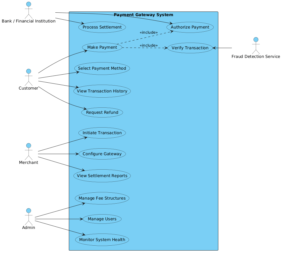
Below is the complete blueprint for the Payment Gateway Use Case diagram. You can visualize the end result immediately and copy the source code to test it in the VPasCode editor.
@startuml
!include https://static.visual-paradigm.com/web/resources/plantuml-stdlib/themes/vp.puml

left to right direction
skinparam packageStyle rectangle

actor Customer
actor Merchant
actor "Bank / Financial Institution" as Bank
actor "Fraud Detection Service" as Fraud
actor Admin

rectangle "Payment Gateway System" {
    Customer --> (Make Payment)
    Customer --> (Select Payment Method)
    Customer --> (View Transaction History)
    Customer --> (Request Refund)

    Merchant --> (Initiate Transaction)
    Merchant --> (Configure Gateway)
    Merchant --> (View Settlement Reports)

    Admin --> (Manage Users)
    Admin --> (Monitor System Health)
    Admin --> (Manage Fee Structures)

    (Make Payment) ..> (Authorize Payment) : <<include>>
    (Make Payment) ..> (Verify Transaction) : <<include>>

    Bank --> (Authorize Payment)
    Bank --> (Process Settlement)

    (Verify Transaction) <-- Fraud
}

@endumlStep-by-Step Architectural Walkthrough
Building a professional diagram requires a structured approach. We will construct this Payment Gateway model in four distinct phases, ensuring logical grouping and accurate relationship mapping.
Phase 1: Canvas Configuration & Layout Directives
Before defining actors, we must set the stage. A financial system diagram should be clean and directional. We start by including the VPasCode standard theme to ensure consistent styling across all elements. We then set the direction to left to right, which aligns with Western reading patterns, and define the package style as rectangle to clearly demarcate the system boundary.
!include https://static.visual-paradigm.com/web/resources/plantuml-stdlib/themes/vp.puml
left to right direction
skinparam packageStyle rectangle
Phase 2: Declaring Core Entities, Actors, and Boundaries
Next, we define the external actors. In a Payment Gateway, trust is paramount. We declare the Customer, Merchant, and Admin, but also crucial external partners like the Bank and Fraud Detection Service. These are defined using the actor keyword. We then establish the system boundary using a rectangle labeled “Payment Gateway System”. Everything inside this box represents functionality provided by the gateway itself.
actor Customer
actor Merchant
actor "Bank / Financial Institution" as Bank
actor "Fraud Detection Service" as Fraud
actor Admin

rectangle "Payment Gateway System" {
Phase 3: Mapping Data Flows & Key Interactions
Now we map the relationships. Solid arrows (-->) represent direct interaction, while dashed arrows (..>) represent dependencies. For example, a Customer directly interacts with (Make Payment). However, (Make Payment) includes (Authorize Payment) and (Verify Transaction). This hierarchy is critical for understanding that a payment cannot succeed without these underlying steps. We also model the Fraud service interacting with verification.
Customer --> (Make Payment)
(Make Payment) ..> (Authorize Payment) : <>
(Verify Transaction) <-- Fraud
Phase 4: Grouping, Annotations & Visual Polish
Finally, we ensure all actors are connected to their relevant use cases within the boundary. The Merchant focuses on settlement and configuration, while the Admin handles system health and fee structures. Closing the rectangle and the diagram with @enduml completes the structure. This phase ensures the diagram is not just functional, but readable and professional.
Syntax & Keyword Deep Dive
Understanding the specific PlantUML syntax is key to mastering diagram-as-code. Here are the critical keywords used in this Payment Gateway model:
actor: Defines an external entity interacting with the system. Used forCustomer,Merchant, andBank.rectangle: Creates a system boundary. All use cases inside are considered part of the system's internal functionality.-->: Represents a direct association or interaction between an actor and a use case...>: Represents a dependency relationship, often used for <> or < > scenarios where one use case relies on another. <: A specific stereotype indicating that the base use case (e.g., Make Payment) always incorporates the behavior of the included use case (e.g., Authorize Payment).>
Best Practices & Pitfalls to Avoid
To maintain high-quality architectural documentation, follow these modeling best practices:
- Keep Actors External: Ensure actors are always outside the system boundary rectangle. If an actor is inside, they are part of the system, not a user or external service.
- Use Clear Naming: Use verb-noun phrases for use cases (e.g., "Make Payment" instead of "Payment"). This clarifies the action being taken.
- Manage Complexity: If the diagram becomes too crowded, consider splitting it into subsystems. A single diagram with 50+ use cases is often unreadable.
- Consistent Relationships: Distinguish clearly between direct interaction (
-->) and logical dependency (..>). Mixing these up can confuse stakeholders about system responsibilities.
Start Building PlantUML Diagrams Faster with VPasCode
Test, preview, and customize this Payment Gateway diagram online in VPasCode without installing any tools or configuring local environments.