


In the rapidly evolving fintech landscape, clarity in financial workflows is not just a nicety—it is a regulatory and operational necessity. Whether you are architecting a microfinance application or a banking gateway, understanding the lifecycle of a loan disbursement is critical. A single misstep in the logic flow can lead to financial discrepancies, compliance breaches, or poor user experiences.

Traditional drag-and-drop diagramming tools often become static snapshots that fall out of sync with the codebase. This is where diagram-as-code shines. By defining your workflow logic in text, specifically using PlantUML, you ensure your documentation remains versioned, editable, and integrated into your development lifecycle. In this masterclass, we utilize VPasCode, the free web-based PlantUML editor, to build a professional Activity Diagram for a Microloan Disbursement process. This approach allows you to prototype complex branching logic and parallel processing flows instantly without installing Java or local dependencies.
Understanding the Model: Purpose, Scope & Problem Framing
Before diving into the syntax, it is essential to understand the architectural abstraction we are modeling. An Activity Diagram is ideal for this scenario because it focuses on the dynamic behavior of the system—the flow of control and data—rather than static structure.
Diagram Abstraction & Representation
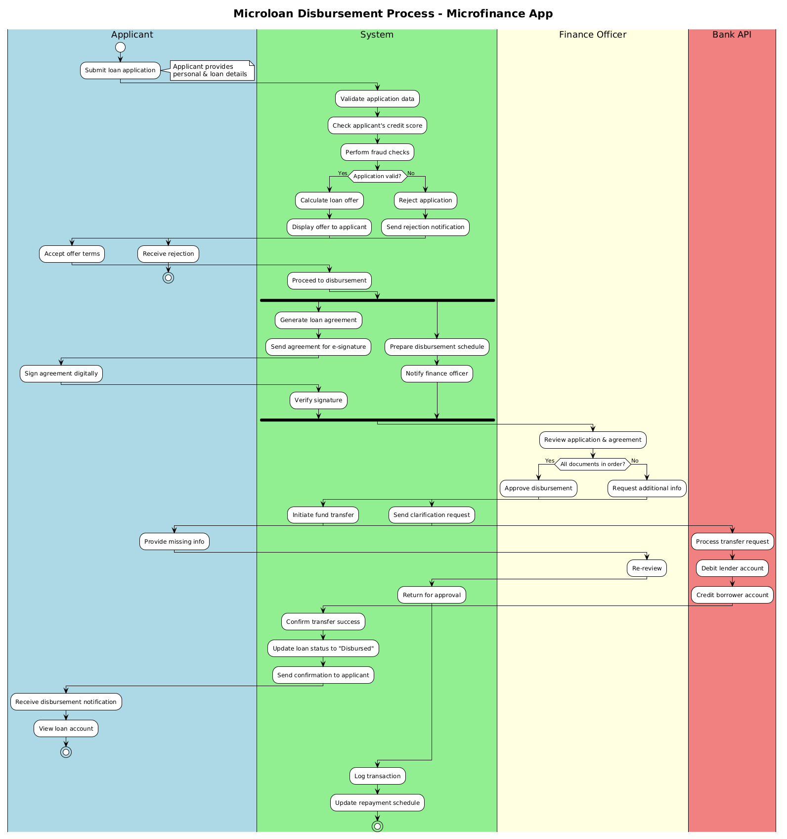
This diagram models the Microloan Disbursement Process. It visualizes the journey of a loan request from the initial submission by a user to the final fund transfer. The use of swimlanes is critical here; they partition the diagram into distinct responsibilities. We are not just drawing boxes; we are defining system boundaries:
- Applicant: The external actor initiating the request.
- System: The core application logic handling validation and orchestration.
- Finance Officer: The human-in-the-loop for compliance review.
- Bank API: The external financial infrastructure executing the transaction.
Target Domain Scope & Scenario
The scope of this model covers the successful and failed paths of a loan request. It explicitly handles conditional logic (credit checks, document verification) and parallel processing (generating agreements while notifying officers). This ensures that developers and stakeholders can visualize exactly where bottlenecks might occur or where automated decisions replace human intervention.
Key Takeaways & Educational Insights
By constructing this diagram in VPasCode, you will gain insights into:
- How to structure complex financial workflows using swimlanes.
- How to represent parallel tasks using
forkandfork againsyntax. - How to manage error handling and rejection paths effectively.
Complete Diagram & Full Source Code
Below is the finalized blueprint for the Microloan Disbursement process. You can view the rendered output immediately below the code block in the VPasCode editor interface.
@startuml
!theme plain
title Microloan Disbursement Process - Microfinance App

|#LightBlue|Applicant|
|#LightGreen|System|
|#LightYellow|Finance Officer|
|#LightCoral|Bank API|

|Applicant|
start
:Submit loan application;
note right
  Applicant provides
  personal & loan details
end note

|System|
:Validate application data;
:Check applicant's credit score;
:Perform fraud checks;

if (Application valid?) then (Yes)
  :Calculate loan offer;
  :Display offer to applicant;
  |Applicant|
  :Accept offer terms;
  |System|
  :Proceed to disbursement;
else (No)
  :Reject application;
  :Send rejection notification;
  |Applicant|
  :Receive rejection;
  stop
endif

|System|
fork
  :Generate loan agreement;
  :Send agreement for e-signature;
  |Applicant|
  :Sign agreement digitally;
  |System|
  :Verify signature;
fork again
  :Prepare disbursement schedule;
  :Notify finance officer;
end fork

|Finance Officer|
:Review application & agreement;
if (All documents in order?) then (Yes)
  :Approve disbursement;
  |System|
  :Initiate fund transfer;
  |Bank API|
  :Process transfer request;
  :Debit lender account;
  :Credit borrower account;
  |System|
  :Confirm transfer success;
  :Update loan status to "Disbursed";
  :Send confirmation to applicant;
  |Applicant|
  :Receive disbursement notification;
  :View loan account;
  stop
else (No)
  |Finance Officer|
  :Request additional info;
  |System|
  :Send clarification request;
  |Applicant|
  :Provide missing info;
  |Finance Officer|
  :Re-review;
  |System|
  :Return for approval;
endif

|System|
:Log transaction;
:Update repayment schedule;
stop
@endumlStep-by-Step Architectural Walkthrough
Building a robust diagram requires a structured approach. We will break down the construction of this model into four logical phases to ensure clarity and maintainability.
Phase 1: Canvas Configuration & Layout Directives
Every PlantUML diagram starts with initialization directives that set the visual theme and metadata. In this case, we define the title and the visual style.
First, we declare the diagram type using @startuml. We then apply the !theme plain directive to ensure a clean, professional look without heavy graphical decorations, which is ideal for technical documentation.
@startuml
!theme plain
title Microloan Disbursement Process - Microfinance App
This setup ensures that when you render the diagram in VPasCode, the title is prominent and the background is neutral, allowing the flow logic to stand out.
Phase 2: Declaring Core Entities, Actors, and Boundaries
Next, we define the swimlanes. Swimlanes are the backbone of this diagram, separating responsibilities. In PlantUML, swimlanes are defined using the pipe syntax |Color|RoleName|.
|#LightBlue|Applicant|
|#LightGreen|System|
|#LightYellow|Finance Officer|
|#LightCoral|Bank API|
Here, we assign distinct colors to each actor. This visual cue helps stakeholders immediately identify which part of the system is responsible for a specific action. For example, Bank API tasks are isolated in Coral, distinguishing external system calls from internal logic.
Phase 3: Mapping Data Flows & Key Interactions
With the canvas ready, we map the flow. We begin with the start node and move through the initial application submission.
|Applicant|
start
:Submit loan application;
note right
  Applicant provides
  personal & loan details
end note
We then transition to the System lane for validation. The core logic here involves a decision point. We use the if statement to branch the flow based on data validity.
if (Application valid?) then (Yes)
  :Calculate loan offer;
else (No)
  :Reject application;
  stop
endif
This structure ensures that invalid applications are terminated early, preventing unnecessary downstream processing.
Phase 4: Grouping, Annotations & Visual Polish
Complex processes often require parallel actions. In the disbursement phase, the system must generate an agreement while simultaneously notifying the finance officer. We achieve this using the fork directive.
fork
  :Generate loan agreement;
  :Send agreement for e-signature;
  |Applicant|
  :Sign agreement digitally;
  |System|
  :Verify signature;
fork again
  :Prepare disbursement schedule;
  :Notify finance officer;
end fork
This fork block runs two independent threads simultaneously. Once both branches complete, the flow merges, ensuring the finance officer is notified only after the agreement generation logic is initiated. Finally, we ensure every path ends with a stop node to signify process completion.
Syntax & Keyword Deep Dive
To master PlantUML activity diagrams, you must understand the specific keywords that control flow and appearance. Here is a breakdown of the critical syntax used in this tutorial:
start: Marks the entry point of the activity diagram. It is the root node from which all actions begin.stop: Marks the termination point of a specific flow path. Every branch should logically lead to a stop node.note right/note left: Used to add explanatory annotations to specific actions without cluttering the flow lines.if (Condition) then (Yes) else (No) endif: Implements conditional logic. The diagram renders two distinct paths based on the boolean outcome of the condition.fork/fork again/end fork: Defines parallel processing threads.forkstarts the parallel section,fork againadds another parallel branch, andend forkmerges them back into a single flow.|Color|Role|: Defines a swimlane. The color code (hex) allows for visual grouping, while the role name defines the boundary.
Best Practices & Pitfalls to Avoid
When creating financial workflow diagrams, accuracy is paramount. Follow these best practices to maintain high-quality documentation:
- Keep Swimlanes Logical: Do not mix responsibilities. Ensure that the System lane handles automation and the Finance Officer lane handles manual reviews. Mixing them creates ambiguity.
- Use Descriptive Labels: Avoid generic labels like “Process.” Use action-oriented verbs like “Validate application data” or “Initiate fund transfer.” This reduces cognitive load for readers.
- Manage Complexity: If a diagram becomes too large, consider splitting it into sub-processes. A single diagram for the entire loan lifecycle might be overwhelming; focus on the disbursement phase as we did here.
- Test with VPasCode: Always preview your changes in VPasCode. Small syntax errors, like missing
endifor mismatchedforkblocks, can break the rendering. The live editor catches these instantly.
Start Building PlantUML Diagrams Faster with VPasCode
Instantly test, preview, and customize this microfinance workflow diagram online in VPasCode without installing any tools.