


In the realm of Industrial Automation and Manufacturing, precision is not just a goal—it is a requirement. Complex assembly lines involving robotic arms, conveyors, and quality control checkpoints generate vast amounts of process data. However, the true value lies in how clearly these workflows are communicated to engineers, operators, and stakeholders. A well-structured activity diagram serves as the architectural blueprint for these operations, visualizing the sequence of actions, decision points, and parallel processes that define the production lifecycle.

Traditional diagramming tools often require heavy installation, licensing fees, or complex configuration to render professional diagrams. VPasCode (Visual Paradigm’s free web-based diagram editor) changes this paradigm. By leveraging PlantUML, engineers can define complex manufacturing logic using simple text code, instantly rendering professional diagrams in the browser. This approach supports rapid prototyping, living documentation, and immediate validation of assembly logic without the friction of environment setup.
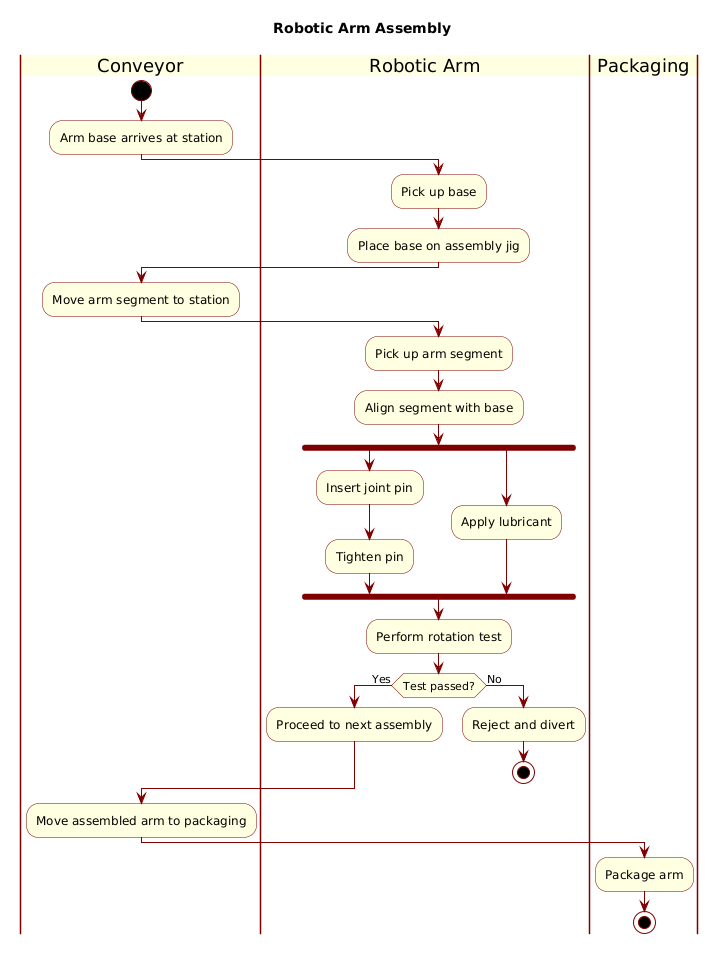
In this masterclass, we will construct a detailed PlantUML activity diagram representing a Robotic Arm Assembly Line Process. This model illustrates how components move through conveyor stations, how robotic arms manipulate parts, and how quality control decisions dictate the flow of the production line.
Understanding the Model: Purpose, Scope & Problem Framing
Before diving into the syntax, it is essential to understand the modeling abstraction we are applying. An activity diagram is the ideal notation for this scenario because it focuses on the behavior of the system over time, rather than its static structure.
Diagram Abstraction & Representation
This diagram models a state-transition workflow. Unlike a class diagram which defines data structures, or a sequence diagram which focuses on object messaging, an activity diagram answers the question: “What happens next?”. It captures the flow of control from the arrival of a base component to the final packaging of the assembled arm. It explicitly defines responsibilities through swimlanes, ensuring that the role of the Conveyor system is distinct from the Robotic Arm and the Packaging unit.
Target Domain Scope & Scenario
The scope of this model is limited to the assembly station itself. We are not modeling the upstream supply chain or the downstream logistics of shipping. The boundaries are defined by the entry of the “Arm base” and the exit of the “Packaged arm”. This focus allows us to drill down into the specific technical interactions, such as the fork/join logic required for parallel lubrication and pin insertion, which are critical for the mechanical integrity of the assembly.
Key Takeaways & Educational Insights
- Swimlane Clarity: Understand how to separate responsibilities between automated hardware (Conveyor) and active machinery (Robotic Arm).
- Parallel Processing: Learn to model concurrent tasks (like inserting pins and applying lubricant) using PlantUML fork syntax.
- Decision Logic: Implement quality control gates where process flow diverges based on test results.
Complete Diagram & Full Source Code
Below is the finished blueprint for the Robotic Arm Assembly process. You can view the rendered output immediately using the interactive editor functionality below.
@startuml
!include https://static.visual-paradigm.com/web/resources/plantuml-stdlib/themes/rose.puml

title Robotic Arm Assembly

|Conveyor|
start
:Arm base arrives at station;

|Robotic Arm|
:Pick up base;
:Place base on assembly jig;

|Conveyor|
:Move arm segment to station;

|Robotic Arm|
:Pick up arm segment;
:Align segment with base;

fork
  :Insert joint pin;
  :Tighten pin;
fork again
  :Apply lubricant;
end fork

:Perform rotation test;

if (Test passed?) then (Yes)
  :Proceed to next assembly;
else (No)
  :Reject and divert;
  stop
endif

|Conveyor|
:Move assembled arm to packaging;

|Packaging|
:Package arm;

stop
@endumlStep-by-Step Architectural Walkthrough
Building this diagram in VPasCode is a structured process. We will break down the construction into four distinct phases, ensuring you understand not just how to write the code, but why each element is placed where it is.
Phase 1: Canvas Configuration & Layout Directives
Every professional diagram starts with a theme and a title. This sets the visual tone and context for the reader. In PlantUML, we use directives to include external style libraries.
We begin by including the rose.puml theme, which provides a clean, modern aesthetic suitable for technical documentation. We then define the diagram title to ensure the context is clear immediately.
!include https://static.visual-paradigm.com/web/resources/plantuml-stdlib/themes/rose.puml

title Robotic Arm Assembly
Phase 2: Declaring Core Entities, Actors, and Boundaries
Swimlanes are the backbone of this diagram. They allow us to partition the workflow by system component. In PlantUML, swimlanes are defined using the pipe character | surrounding the lane name.
We define three primary lanes: |Conveyor| for transport, |Robotic Arm| for manipulation, and |Packaging| for final processing. This separation helps readers quickly identify which subsystem is responsible for each action.
|Conveyor|
start
:Arm base arrives at station;

|Robotic Arm|
:Pick up base;
:Place base on assembly jig;
Phase 3: Mapping Data Flows & Key Interactions
This phase covers the core logic of the assembly. We move from linear flow to parallel execution using the fork keyword. This is critical for modeling real-world manufacturing where multiple tools might operate simultaneously to reduce cycle time.
We also implement a decision node using the if syntax. This represents the quality control checkpoint. If the test fails, the process diverts to a reject state and stops. If it passes, the flow continues.
fork
  :Insert joint pin;
  :Tighten pin;
fork again
  :Apply lubricant;
end fork

:Perform rotation test;

if (Test passed?) then (Yes)
  :Proceed to next assembly;
else (No)
  :Reject and divert;
  stop
endif
Phase 4: Grouping, Annotations & Visual Polish
The final phase ensures the diagram terminates correctly and transitions to the next stage. We use the stop keyword to explicitly end the flow when a component is rejected or successfully packaged. We also ensure the final swimlane |Packaging| is clearly defined to close the process loop.
|Conveyor|
:Move assembled arm to packaging;

|Packaging|
:Package arm;

stop
Syntax & Keyword Deep Dive
To fully master PlantUML activity diagrams, you must understand the specific keywords used to control flow and structure. Here is a breakdown of the critical syntax elements in this diagram:
!include: Allows you to import external style sheets or libraries. In this case, it loads the rose.puml theme to standardize colors and fonts.title: Defines the main heading of the diagram. This is crucial for documentation indexing.|Lane Name|: Defines a swimlane. Everything following this directive until the next lane definition belongs to that specific actor or system.start/stop: Marks the entry and exit points of the activity.startis a filled circle, whilestopis a filled circle with a border.fork/fork again/end fork: Creates parallel branches of execution.forksplits the flow,fork againadds more parallel branches, andend forkmerges them back into a single flow.if (Condition) then (Label): Creates a decision diamond. The text in parentheses represents the label on the outgoing arrow (e.g., “Yes” or “No”).:Action: Defines a standard activity step. The text after the colon describes the action being performed.
Best Practices & Pitfalls to Avoid
When creating diagrams with VPasCode and PlantUML, following established patterns ensures your documentation remains maintainable and clear.
- Keep Swimlanes Balanced: Avoid having one swimlane contain 90% of the logic while others are empty. If a lane is sparse, consider merging it with another to reduce visual noise.
- Use Descriptive Labels: Instead of
:Action, use:Verify Torque Settings. Specificity reduces ambiguity for engineers reading the diagram later. - Limit Parallelism: While
forkis powerful, excessive branching can make the diagram unreadable. Only use parallel flows when tasks truly happen simultaneously in the physical process. - Consistent Terminology: Ensure terms like “Reject” or “Divert” match the actual terminology used in your manufacturing execution system (MES) to avoid confusion.
Try It Yourself with VPasCode
Start Building PlantUML Activity Diagrams Faster with VPasCode
Visualize your manufacturing workflows instantly in the browser with zero setup.