


In the complex landscape of financial services, clarity is not just a design preference; it is a regulatory requirement. Pension Management Systems serve as the backbone for retirement security, handling sensitive data, complex contribution rules, and multi-party financial transactions. When architects or business analysts attempt to document these systems using traditional methods, they often face challenges with version drift, inconsistent formatting, and the difficulty of maintaining diagrams alongside evolving codebases.
Diagram-as-code offers a robust solution to these challenges. By defining visual models through text, teams can leverage the precision of code to manage the complexity of financial workflows. Using PlantUML within the VPasCode editor allows you to prototype, validate, and document these critical interactions instantly. This tutorial demonstrates how to construct a professional Use Case Diagram for a Pension Management System, ensuring all stakeholders—from members to fund managers—have a shared understanding of system boundaries and functional requirements.
Understanding the Model: Purpose, Scope & Problem Framing
Before writing a single line of code, it is essential to understand the abstraction being modeled. A Use Case Diagram is a behavioral diagram that captures the functional requirements of a system from the perspective of external actors. It answers the question: “Who can do what within this system?”
Diagram Abstraction & Representation
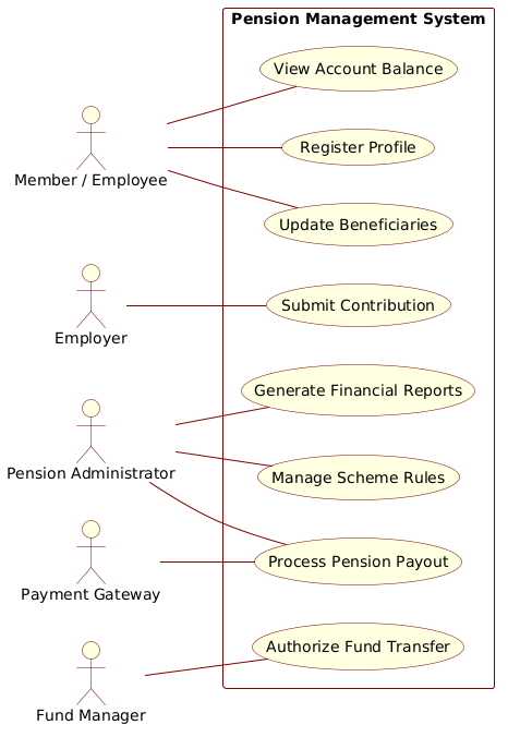
In this financial context, the diagram does not model internal class structures or database schemas. Instead, it models functional interactions. Each Actor represents a distinct user role or external system that interacts with the Pension Management System. Each Use Case represents a specific goal or service the system provides to that actor. This high-level view is critical for defining the system boundary and ensuring no critical financial function is overlooked during the development phase.
Target Domain Scope & Scenario
This model specifically addresses the core operational loop of a pension scheme. The scope includes:
- Primary Actors: Individuals (Members/Employees) managing their retirement, and Employers handling contributions.
- Administrative Actors: Administrators managing rules and payouts, and Fund Managers overseeing investment authorizations.
- External Systems: Banks or Payment Gateways facilitating the actual movement of funds.
By isolating these interactions, we ensure the system design accommodates the specific compliance and security needs of the finance industry without over-engineering the user interface.
Key Takeaways & Educational Insights
Through this tutorial, you will gain insights into how to structure a financial system model using text. You will learn how to group functionality logically within a system boundary, how to distinguish between primary and secondary actors, and how to use VPasCode to visualize these relationships instantly without installing local dependencies.
Complete Diagram & Full Source Code
Below is the complete blueprint for the Pension Management System Use Case Diagram. This code defines the actors, the system boundary, and the specific interactions required for a compliant financial workflow.
Copy the full source code below to visualize the diagram:
@startuml
!include https://static.visual-paradigm.com/web/resources/plantuml-stdlib/themes/rose.puml

left to right direction
skinparam packageStyle rectangle
skinparam defaultTextAlignment center

' Actors
actor "Member / Employee" as Member
actor "Employer" as Employer
actor "Pension Administrator" as Admin
actor "Fund Manager" as FundManager
actor "Payment Gateway" as Bank

rectangle "Pension Management System" {
    usecase "Register Profile" as UC1
    usecase "View Account Balance" as UC2
    usecase "Update Beneficiaries" as UC3
    usecase "Submit Contribution" as UC4
    usecase "Manage Scheme Rules" as UC5
    usecase "Process Pension Payout" as UC6
    usecase "Generate Financial Reports" as UC7
    usecase "Authorize Fund Transfer" as UC8
}

' Primary Actors (Left)
Member -- UC1
Member -- UC2
Member -- UC3

Employer -- UC4

Admin -- UC5
Admin -- UC6
Admin -- UC7

' Secondary Actors (Right)
FundManager -- UC8
Bank -- UC6
@endumlStep-by-Step Architectural Walkthrough
Building this diagram in VPasCode is a structured process. We will break down the construction into four distinct phases to ensure architectural clarity and maintainability.
Phase 1: Canvas Configuration & Layout Directives
The first step in any PlantUML project is setting the canvas environment. We begin by including the theme library to ensure the diagram adheres to professional styling standards. We also define the global layout direction.
!include https://static.visual-paradigm.com/web/resources/plantuml-stdlib/themes/rose.puml

left to right direction
skinparam packageStyle rectangle
skinparam defaultTextAlignment center
The !include directive pulls the rose.puml theme, giving the diagram a consistent color palette and shape style. The left to right direction directive ensures the flow of actors and use cases reads naturally from left to right, which is standard for financial process maps.
Phase 2: Declaring Core Entities, Actors, and Boundaries
Next, we define the participants in the system. In PlantUML, actors are declared using the actor keyword. We assign aliases (like Member) to keep the diagram clean while retaining readable labels.
actor "Member / Employee" as Member
actor "Employer" as Employer
actor "Pension Administrator" as Admin
actor "Fund Manager" as FundManager
actor "Payment Gateway" as Bank

rectangle "Pension Management System" {
    usecase "Register Profile" as UC1
    usecase "View Account Balance" as UC2
    usecase "Update Beneficiaries" as UC3
    usecase "Submit Contribution" as UC4
    usecase "Manage Scheme Rules" as UC5
    usecase "Process Pension Payout" as UC6
    usecase "Generate Financial Reports" as UC7
    usecase "Authorize Fund Transfer" as UC8
}
The rectangle block defines the system boundary. Anything inside is part of the Pension Management System. The usecase keyword defines the specific functional goals, such as Submit Contribution or Process Pension Payout. Grouping these inside the rectangle visually communicates that these functions are encapsulated within the system.
Phase 3: Mapping Data Flows & Key Interactions
With entities and boundaries defined, we map the relationships. The solid line with arrows (or just lines in this case) represents the association between an actor and a use case.
' Primary Actors (Left)
Member -- UC1
Member -- UC2
Member -- UC3

Employer -- UC4

Admin -- UC5
Admin -- UC6
Admin -- UC7

' Secondary Actors (Right)
FundManager -- UC8
Bank -- UC6
Here, we explicitly link the Member to their profile management tasks. The Employer is linked specifically to contributions. The Admin handles the heavy lifting of rules and payouts. The Bank is linked to UC6 (Payout) because the bank executes the transaction, while the FundManager links to UC8 (Fund Transfer) to authorize investments.
Phase 4: Grouping, Annotations & Visual Polish
Finally, we ensure the visual hierarchy is clear. The skinparam directives used in Phase 1 handle the alignment and style. In VPasCode, you can instantly adjust these parameters to see how they affect the layout. For example, changing packageStyle to folder would alter the boundary shape, allowing you to test different visual metaphors for your documentation.
Syntax & Keyword Deep Dive
Understanding the specific PlantUML syntax is crucial for extending this diagram later. Here are the key components used:
actor: Defines a role or external system interacting with the system. Can be rendered as a stick figure or a specific icon.usecase: Defines an oval representing a specific function or goal within the system boundary.rectangle: Creates a container to group use cases, visually defining the system boundary.--: The association operator. It connects actors to use cases to show interaction.skinparam: Global styling commands.skinparam packageStyle rectangleforces the system boundary to be a rectangle rather than a rounded box.left to right direction: A layout directive that forces the rendering engine to arrange elements horizontally.
Best Practices & Pitfalls to Avoid
When modeling financial systems, precision is key. Follow these best practices to maintain high-quality documentation:
- Maintain Abstraction Levels: Do not mix high-level use cases (e.g., “Manage Scheme Rules”) with low-level technical actions (e.g., “Update SQL Database”). Keep the diagram focused on user goals.
- Clear Actor Naming: Use specific names like “Employer” rather than generic “User.” This clarifies compliance roles and permissions.
- Boundary Discipline: Only include use cases that fall strictly within the system scope. External dependencies like the
Bankshould be actors, not use cases. - Modular Code: As the system grows, split use cases into separate files and include them. This keeps your PlantUML source code manageable.
Try It Yourself with VPasCode
Start Building Financial Use Case Diagrams Faster with VPasCode
Instantly prototype, preview, and customize your Pension Management System diagram online in VPasCode without installing any tools.