


Introduction: Visualizing Financial Security Workflows
In the high-stakes world of fintech and digital banking, the integrity of transaction processing is paramount. A single fraudulent transaction can erode trust, incur financial loss, and trigger regulatory scrutiny. To maintain robust security posture, architects and security engineers must clearly define the logic flows that govern fraud detection. This is where visual modeling becomes critical.

While code-based documentation is powerful, it often lacks the immediate visual clarity required to communicate complex decision trees to stakeholders. An Activity Diagram provides the perfect abstraction for mapping the lifecycle of a transaction from initiation to final settlement. By using diagram-as-code with PlantUML in VPasCode, teams can rapidly prototype these security workflows, ensuring that parallel checks, risk scoring, and manual review loops are logically sound before deployment.
This tutorial demonstrates how to build a professional Credit Card Fraud Detection Activity Diagram. We will leverage swimlanes to separate responsibilities, parallel forks for concurrent risk checks, and conditional logic for manual intervention. Using the VPasCode web editor, you can write this code once and instantly visualize the architecture without any local environment setup.
Understanding the Model: Purpose, Scope & Problem Framing
Before writing a single line of code, it is essential to understand the architectural abstraction we are constructing. This model represents a standard synchronous transaction flow enhanced with asynchronous security checks.
Diagram Abstraction & Representation
An Activity Diagram is best suited for this scenario because it focuses on the flow of control rather than static structure. In the context of fraud detection, the diagram models the state transitions of a transaction. It answers critical questions: Who initiates the action? Which systems validate the data? What happens when a threshold is breached?
We utilize swimlanes to enforce separation of duties. This visualizes the boundary between the end-user (Customer), the infrastructure (Payment Gateway), and the security logic (Fraud Detection). This clarity is vital for compliance audits, as it explicitly shows where the responsibility lies for rejecting a transaction versus approving it.
Target Domain Scope & Scenario
This diagram covers the end-to-end process of a single credit card transaction. It intentionally excludes external dependencies like bank account verification or 3D Secure authentication to focus purely on the internal fraud scoring mechanism. The scope includes:
- Initiation: The customer submits a payment request.
- Routing: The gateway passes data to the security engine.
- Analysis: Parallel checks on amount limits and geolocation.
- Decision: A risk score calculation leading to a binary decision (Suspicious vs. Normal).
- Resolution: Either immediate acceptance or a manual review loop.
Key Takeaways & Educational Insights
By the end of this guide, you will understand how to model complex conditional logic using PlantUML syntax. You will learn how to structure swimlanes to reflect organizational boundaries and how to implement parallel processing (forks) to simulate concurrent security checks. This knowledge translates directly to better system design, clearer documentation, and faster onboarding for new developers joining the fintech team.
Complete Diagram & Full Source Code
Below is the finished blueprint of the Credit Card Fraud Detection Process. You can copy this code directly into the VPasCode editor to see the live rendering.
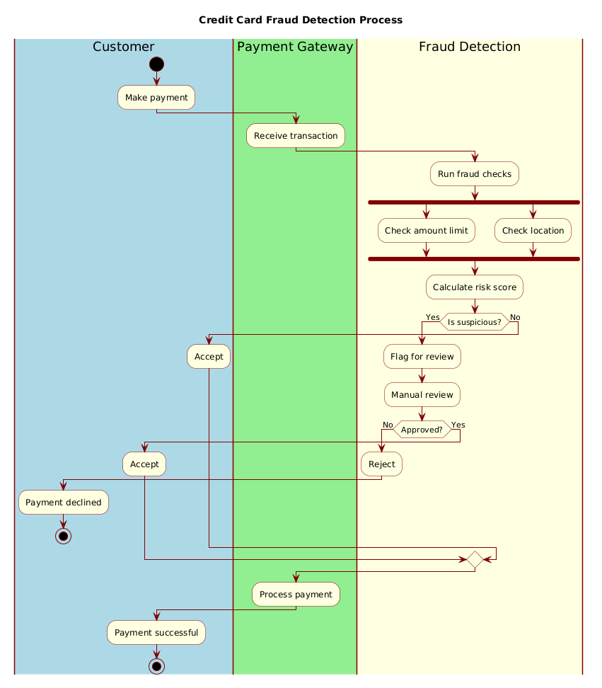
@startuml
!include https://static.visual-paradigm.com/web/resources/plantuml-stdlib/themes/rose.puml

title Credit Card Fraud Detection Process

|#LightBlue|Customer|
|#LightGreen|Payment Gateway|
|#LightYellow|Fraud Detection|

|Customer|
start
:Make payment;

|Payment Gateway|
:Receive transaction;

|Fraud Detection|
:Run fraud checks;

fork
  :Check amount limit;
fork again
  :Check location;
end fork

:Calculate risk score;

if (Is suspicious?) then (Yes)
  :Flag for review;
  :Manual review;

  if (Approved?) then (No)
    :Reject;
    |Customer|
    :Payment declined;
    stop
  else (Yes)
    :Accept;
  endif
else (No)
  :Accept;
endif

|Payment Gateway|
:Process payment;

|Customer|
:Payment successful;

stop

@endumlStep-by-Step Architectural Walkthrough
Now that you have the complete diagram, let’s deconstruct how we built it. We will break the implementation into four logical phases, mirroring the architectural design process.
Phase 1: Canvas Configuration & Layout Directives
Every PlantUML diagram begins with configuration directives that define the rendering engine and the visual theme. For a finance application, a clean, professional look is essential. We start by including a standard library theme to ensure consistent styling across all components.
!include https://static.visual-paradigm.com/web/resources/plantuml-stdlib/themes/rose.pumlNext, we define the diagram title. This metadata appears at the top of the rendered diagram and is crucial for documentation indexing.
title Credit Card Fraud Detection ProcessPhase 2: Declaring Core Entities, Actors, and Boundaries
The core of this model is the swimlane structure. Swimlanes allow us to map system components to specific visual rows. In PlantUML, we define these using the pipe syntax `|#Color|Name|`. This ensures that the visual output matches the logical ownership of the data.
|#LightBlue|Customer|
|#LightGreen|Payment Gateway|
|#LightYellow|Fraud Detection|
Notice how we assign specific colors to each lane. This visual cue helps stakeholders instantly identify which actor is responsible for the current step in the workflow.
Phase 3: Mapping Data Flows & Key Interactions
With the canvas ready, we define the flow of control. We start with the entry point using the `start` keyword. The flow moves vertically through the swimlanes, crossing boundaries to represent system-to-system communication.
|Customer|
start
:Make payment;

|Payment Gateway|
:Receive transaction;
A critical architectural pattern here is the Fork. In fraud detection, checks like “Amount Limit” and “Location” often happen simultaneously to save latency. We use the `fork` and `fork again` keywords to represent this parallel execution.
fork
  :Check amount limit;
fork again
  :Check location;
end fork
After the parallel checks, the flow merges back into a single path to calculate a composite risk score.
Phase 4: Grouping, Annotations & Visual Polish
The final phase involves handling the decision logic. Fraud detection is rarely a straight line; it requires branching paths for exceptions. We use the `if` keyword to create conditional branches. If the transaction is flagged as suspicious, the flow enters a manual review loop.
if (Is suspicious?) then (Yes)
  :Flag for review;
  :Manual review;
  if (Approved?) then (No)
    :Reject;
    |Customer|
    :Payment declined;
    stop
  else (Yes)
    :Accept;
  endif
else (No)
  :Accept;
endif
Finally, we ensure every path terminates correctly using the `stop` keyword. This prevents ambiguity in the workflow and ensures the diagram is syntactically complete.
Syntax & Keyword Deep Dive
To master PlantUML activity diagrams, you must understand the specific keywords used to control flow and structure. Here is a breakdown of the critical syntax elements used in this tutorial:
start: Marks the initial point of the activity. Every valid activity diagram must have exactly one start node.stop: Marks the termination point. In complex diagrams with multiple branches, ensure all paths lead to a stop node to avoid orphaned flows.fork / fork again / end fork: These keywords enable parallel processing.forksplits the flow into multiple simultaneous paths,fork againadds more parallel branches, andend forkmerges them back into a single flow.if / then / else / endif: Standard conditional logic. The syntax allows you to define the condition in parentheses `()` and label the branches with `then (Label)` or `else (Label)`.|#Color|Name|: Defines a swimlane. The color hex code or name defines the background, and the text defines the role. You can switch lanes mid-flow by referencing the lane name again.title: Sets the main caption of the diagram, displayed prominently at the top.
Best Practices & Pitfalls to Avoid
When modeling financial workflows, clarity is more important than complexity. Follow these best practices to maintain high-quality diagrams:
- Keep Swimlanes Logical: Do not create too many swimlanes. If you find yourself adding a new lane for every minor function, consider grouping them into a single “System” lane. In this guide, we kept it to three distinct actors for maximum clarity.
- Consistent Naming Conventions: Use imperative verbs for actions (e.g., “Make payment”, “Receive transaction”) rather than nouns. This implies action and movement, which fits the nature of an activity diagram.
- Handle All Exit Paths: A common pitfall is forgetting a path in a conditional statement. Always verify that every `if` block has a corresponding `stop` or merge point, even in the error/rejection scenarios.
- Use Themes for Professionalism: Don’t rely on default styling. Including a theme like `rose.puml` or `blue.puml` immediately elevates the diagram from a sketch to a professional architectural artifact.
Try It Yourself with VPasCode
Start Building PlantUML Activity Diagrams Faster with VPasCode
Instantly prototype, preview, and customize your Credit Card Fraud Detection workflow online in VPasCode without installing any tools.