


In the modern fintech landscape, cross-border remittance systems represent some of the most critical and complex financial architectures. These platforms must seamlessly handle client requests, validate regulatory compliance, calculate dynamic foreign exchange rates, and route payments through various clearing networks. For software architects and developers, documenting this intricate flow is challenging using traditional drawing tools, which often become static and difficult to maintain.

Diagramming-as-code with PlantUML within VPasCode offers a superior alternative. By treating architecture documentation as versionable, text-based source code, teams can ensure their visual models remain synchronized with the actual system design. This tutorial leverages VPasCode, a free web-based diagram-as-code editor, to demonstrate how to build a professional component diagram for a Cross-Border Remittance System. This approach enhances architectural clarity, enables rapid visual prototyping, and creates living technical documentation that is easy to share and update.
Understanding the Model: Purpose, Scope & Problem Framing
Before writing a single line of code, it is essential to understand the abstraction and domain scope of the model we are building. This specific diagram type serves as a structural blueprint for the system.
Diagram Abstraction & Representation
A PlantUML component diagram models the physical or logical building blocks of a system. In the context of finance, these components represent distinct services or modules that encapsulate specific responsibilities. We use interfaces (depicted as balls and sockets) to define the contracts between these components. This allows us to visualize dependencies without exposing internal implementation details, which is crucial for maintaining system modularity and security in high-stakes financial environments.
Target Domain Scope & Scenario
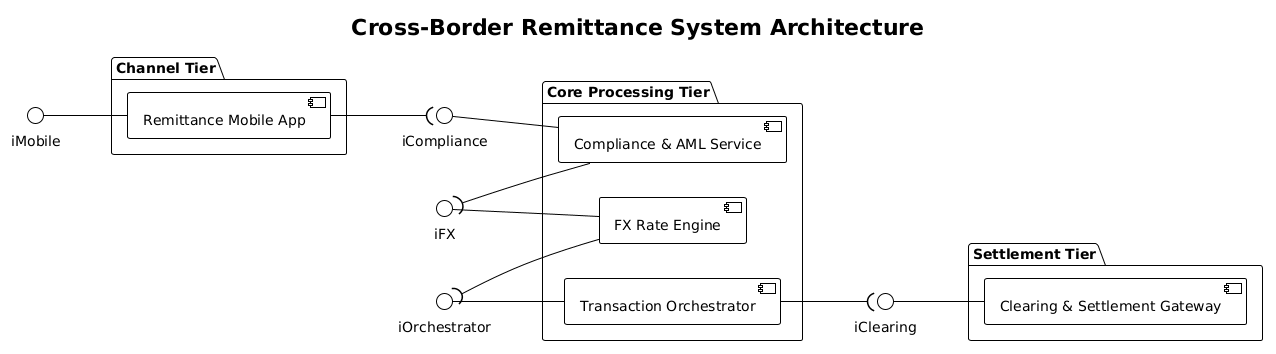
This model focuses on the end-to-end flow of an international money transfer. It intentionally boundaries the system into three logical tiers:
- Channel Tier: The entry point where users initiate transactions (e.g., mobile applications).
- Core Processing Tier: The brain of the operation, handling logic, compliance checks, and currency conversion.
- Settlement Tier: The execution layer responsible for moving funds through banking networks.
By isolating these tiers, we can analyze how data flows from a user request to final settlement, identifying potential bottlenecks in compliance or FX processing.
Key Takeaways & Educational Insights
Through this guide, you will gain insights into how to structure a financial system diagram using packages and interfaces. You will learn how to use VPasCode to instantly render these diagrams, ensuring your architectural documentation is accurate and up-to-date without the overhead of manual drawing tools.
Complete Diagram & Full Source Code
Below is the finished blueprint for the Cross-Border Remittance System. You can view the rendered result immediately in the VPasCode editor.
@startuml
!theme plain


title Cross-Border Remittance System Architecture
/'
This component diagram depicts the system architecture for an international money transfer and remittance platform. It illustrates the structured workflow from client-facing initiation channels through compliance validation, foreign exchange processing, and multi-rail payment delivery networks.
'/

left to right direction

skinparam componentStyle uml2

package "Channel Tier" {
  [Remittance Mobile App] as MobileApp
}

package "Core Processing Tier" {
  [Compliance & AML Service] as Compliance
  [FX Rate Engine] as FXEngine
  [Transaction Orchestrator] as Orchestrator
}

package "Settlement Tier" {
  [Clearing & Settlement Gateway] as ClearingGateway
}

' Provided Interfaces (on the left)
iMobile -- MobileApp
iCompliance -- Compliance
iFX -- FXEngine
iOrchestrator -- Orchestrator
iClearing -- ClearingGateway

' Required Interfaces (on the right)
MobileApp --( iCompliance
Compliance --( iFX
FXEngine --( iOrchestrator
Orchestrator --( iClearing

@endumlStep-by-Step Architectural Walkthrough
Building this diagram in VPasCode involves four logical phases. Follow this sequence to replicate the architecture.
Phase 1: Canvas Configuration & Layout Directives
Every PlantUML diagram begins with setup commands that define the global behavior of the rendering engine. We start by initializing the diagram and setting the orientation.
title Cross-Border Remittance System Architecture
/'
This component diagram depicts the system architecture...
'/
left to right direction
The title command sets the header. The comment block (wrapped in /' and '/) provides context for the diagram without rendering visually. The left to right direction directive ensures the flow moves horizontally, which is standard for process flows.
Phase 2: Declaring Core Entities, Actors, and Boundaries
Next, we define the structural boundaries using package blocks. In finance, separating concerns into tiers is a best practice for security and scalability.
package "Channel Tier" {
  [Remittance Mobile App] as MobileApp
}

package "Core Processing Tier" {
  [Compliance & AML Service] as Compliance
  [FX Rate Engine] as FXEngine
  [Transaction Orchestrator] as Orchestrator
}
Here, package groups related components. The [Component Name] as Alias syntax defines a component and assigns it a short-hand identifier for use in connections.
Phase 3: Mapping Data Flows & Key Interactions
Components do not exist in isolation; they rely on services. We define these dependencies using interface notation. Provided interfaces are services a component offers, while required interfaces are services a component needs.
iCompliance -- Compliance
Compliance --( iFX
In VPasCode, you can visually verify these connections. The -- line connects a provided interface (left) to a component. The --( line connects a component to a required interface (right), indicating the component depends on that interface.
Phase 4: Grouping, Annotations & Visual Polish
Finally, we apply styling to ensure the diagram looks professional. We set the component style to uml2 for standard box shapes.
skinparam componentStyle uml2
This ensures consistency across the diagram. VPasCode allows you to tweak these skin parameters instantly to match your organization’s branding guidelines.
Syntax & Keyword Deep Dive
Understanding the specific PlantUML syntax is key to mastering diagram-as-code. Here are the critical keywords used in this architecture:
package: Defines a container for grouping related components. Essential for organizing large systems into logical tiers like Channel, Core, and Settlement.skinparam: Used to customize the visual appearance, such as colors, fonts, and component shapes (e.g.,componentStyle uml2).--: The standard connector line. When used asiName -- Component, it indicates a provided interface.--(: The required interface connector. The parenthesis(signifies a socket, meaning the component requires this interface to function.title: Adds a headline to the diagram for immediate context.
Best Practices & Pitfalls to Avoid
To maintain high-quality documentation with VPasCode, adhere to these modeling guidelines:
- Modularize with Packages: Never dump all components into the root. Use
packageblocks to reflect your system’s physical or logical separation (e.g., Frontend vs. Backend). - Consistent Naming: Use clear, descriptive names for components and aliases. Avoid generic names like
Comp1; useFXEngineinstead. - Interface Directionality: Be precise with
--and--(. Placing the interface on the wrong side of the component will invert the visual meaning of who provides and who requires the service. - Keep it Abstract: Do not model every internal method. A component diagram should show *what* the system does, not *how* it implements it internally.
Start Building PlantUML Diagrams Faster with VPasCode
Instantly prototype, preview, and customize your Cross-Border Remittance architecture online in VPasCode without installing any tools.