


In the complex landscape of modern manufacturing, the gap between enterprise-level planning and shop-floor execution is often bridged by a Manufacturing Execution System (MES). These systems are critical for translating high-level business goals into actionable production steps. However, defining the scope and interactions within an MES can be challenging without a clear visual model. Diagramming-as-code with PlantUML offers a robust solution for architects and engineers to document these workflows with precision.

Using VPasCode, the free web-based diagram-as-code editor, teams can rapidly prototype these diagrams without local installation. This approach enhances architectural clarity, allowing stakeholders to visualize how primary actors like Production Supervisors interact with the system versus secondary actors like external ERP systems. By adopting a diagram-as-code methodology, documentation becomes versioned, testable, and instantly shareable, ensuring that the system boundaries and functional requirements are unambiguous from the start.
Understanding the Model: Purpose, Scope & Problem Framing
Before diving into the syntax, it is essential to understand the architectural abstraction this model represents. A Use Case Diagram is not merely a list of features; it is a boundary definition tool that clarifies the “what” of the system from the perspective of the “who”.
Diagram Abstraction & Representation
In this context, the Use Case Diagram models the functional requirements of the MES. Actors represent the roles or external systems that interact with the MES. Primary actors (on the left) are internal roles that initiate workflows, such as the Machine Operator. Secondary actors (on the right) are external systems or personnel that provide data or receive results but do not initiate the core process, such as the ERP System. The system boundary, represented by the rectangle, encapsulates the core logic of the MES, distinguishing internal functionality from external dependencies.
Target Domain Scope & Scenario
This guide focuses specifically on the core functionalities of an MES in a production environment. The scope covers the interaction between floor roles and the system’s ability to manage orders, track work-in-progress (WIP), and handle exceptions. It intentionally excludes detailed sequence logic or data structure specifics, focusing instead on the high-level functional boundaries and actor responsibilities.
Key Takeaways & Educational Insights
By constructing this diagram, you will gain insight into how to separate primary operational roles from external system integrations. You will learn how to define clear system boundaries and how to use PlantUML to maintain a clean, readable model that serves as living documentation for the manufacturing workflow.
Complete Diagram & Full Source Code
Below is the finished blueprint for the Manufacturing Execution System Use Case Diagram. This model demonstrates the proper layout for actors, the definition of the system boundary, and the specific associations required to map the manufacturing workflow.
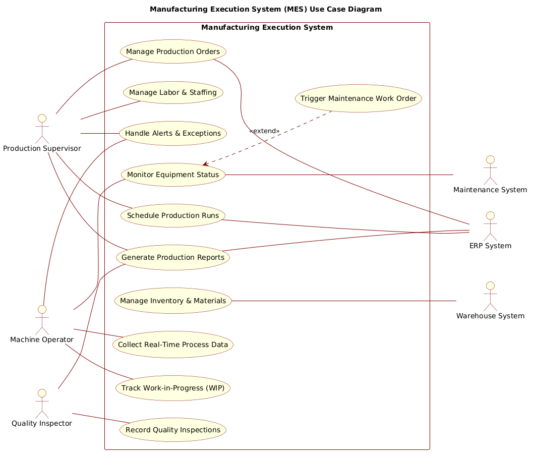
@startuml
!include https://static.visual-paradigm.com/web/resources/plantuml-stdlib/themes/rose.puml

title Manufacturing Execution System (MES) Use Case Diagram

/'
This use case diagram models the core functionalities of a Manufacturing Execution System (MES)
in a production environment. The system bridges the gap between enterprise-level planning (ERP)
and shop-floor control. Primary actors are production floor roles who actively interact with the
system to manage and monitor manufacturing operations. Secondary actors represent external systems
or personnel that provide data or receive information but do not initiate the primary workflows.
'/

left to right direction

rectangle "Manufacturing Execution System" {
  usecase "Manage Production Orders" as UC1
  usecase "Track Work-in-Progress (WIP)" as UC2
  usecase "Record Quality Inspections" as UC3
  usecase "Monitor Equipment Status" as UC4
  usecase "Manage Labor & Staffing" as UC5
  usecase "Generate Production Reports" as UC6
  usecase "Manage Inventory & Materials" as UC7
  usecase "Schedule Production Runs" as UC8
  usecase "Handle Alerts & Exceptions" as UC9
  usecase "Collect Real-Time Process Data" as UC10
  usecase "Trigger Maintenance Work Order" as UC11
}

' Primary Actors (left side)
actor "Production Supervisor" as Supervisor
actor "Machine Operator" as Operator
actor "Quality Inspector" as Inspector

Supervisor -- UC1
Supervisor -- UC8
Supervisor -- UC5
Supervisor -- UC6
Supervisor -- UC9

Operator -- UC2
Operator -- UC4
Operator -- UC10
Operator -- UC9

Inspector -- UC3
Inspector -- UC6

' Extend relationship
UC4 <.. UC11 : <<extend>>
' Extension point: when equipment critical threshold exceeded

' Secondary Actors (right side)
actor "ERP System" as ERP
actor "Maintenance System" as MaintSys
actor "Warehouse System" as WhSys

UC1 --- ERP
UC4 --- MaintSys
UC7 --- WhSys
UC6 --- ERP
UC8 --- ERP

@endumlStep-by-Step Architectural Walkthrough
Building this diagram in VPasCode involves four distinct phases. We will start with the environment setup, define the system boundary, declare the actors, and finally map the relationships.
Phase 1: Canvas Configuration & Layout Directives
Every PlantUML diagram begins with the standard delimiters and optional theme includes. For this manufacturing model, we utilize the Rose theme to provide a professional, clean aesthetic suitable for enterprise documentation. We also set the direction to “left to right” to ensure primary actors appear on the left and secondary actors on the right, which is a common convention for clarity.
@startuml
!include https://static.visual-paradigm.com/web/resources/plantuml-stdlib/themes/rose.puml

title Manufacturing Execution System (MES) Use Case Diagram

/'
This use case diagram models the core functionalities...
'/

left to right direction
The comment block, wrapped in /' and '/, provides context for the diagram without rendering in the final image. This is crucial for maintaining documentation standards.
Phase 2: Declaring Core Entities, Actors, and Boundaries
The system boundary is defined using a rectangle shape. Inside this boundary, we declare the use cases using the usecase keyword. Assigning an alias (e.g., as UC1) allows us to reference these use cases later when drawing connections, keeping the code concise.
rectangle "Manufacturing Execution System" {
  usecase "Manage Production Orders" as UC1
  usecase "Track Work-in-Progress (WIP)" as UC2
  usecase "Record Quality Inspections" as UC3
  // ... other use cases
}
Actors are declared outside the boundary using the actor keyword. We define primary actors (Supervisor, Operator, Inspector) and secondary actors (ERP System, Maintenance System, Warehouse System) separately to maintain logical grouping.
actor "Production Supervisor" as Supervisor
actor "Machine Operator" as Operator
actor "Quality Inspector" as Inspector
Phase 3: Mapping Data Flows & Key Interactions
Once entities are declared, we map their interactions. Associations are drawn using the -- symbol. Note that we avoid arrowheads for standard associations to keep the diagram clean, focusing on the relationship rather than the direction of data flow.
Supervisor -- UC1
Operator -- UC2
Inspector -- UC3
For secondary actors, we use a dashed line --- to indicate they are external dependencies or systems providing data, distinguishing them from human primary actors.
UC1 --- ERP
UC4 --- MaintSys
Phase 4: Grouping, Annotations & Visual Polish
Finally, we add specific relationships like the <<extend>> relationship between Monitoring Equipment Status and Triggering Maintenance. This indicates that maintenance is an optional flow triggered under specific conditions. We ensure the diagram is enclosed with @enduml to complete the script.
UC4 <.. UC11 : <>

@enduml
Syntax & Keyword Deep Dive
Understanding the specific PlantUML syntax is key to mastering diagram-as-code. Here are the critical keywords used in this Manufacturing Execution System model:
@startuml: Marks the beginning of the PlantUML script.title: Defines the main heading displayed at the top of the diagram./' ... '/: Defines a comment block that is rendered in the editor but not in the final image output.left to right direction: Sets the layout flow of the diagram elements horizontally.rectangle: Creates a system boundary box to group use cases together.usecase: Defines a specific functional goal or action within the system.actor: Defines an external entity (human or system) interacting with the system.--: Creates a solid association line between an actor and a use case.---: Creates a dashed association line, often used for external systems.<<extend>>: Denotes an extend relationship where one use case extends another under specific conditions.
Best Practices & Pitfalls to Avoid
To maintain high-quality diagrams in VPasCode, follow these modeling best practices:
- Separate Primary and Secondary Actors: Visually distinguish between internal roles and external systems. Use dashed lines for external systems to clarify boundaries.
- Keep Use Cases Atomic: Each use case should represent a single, distinct goal (e.g., “Record Quality Inspections” rather than “Manage Quality and Safety”).
- Use Meaningful Aliases: Always assign aliases (e.g.,
as UC1) to use cases. This prevents code bloat when drawing multiple associations. - Avoid Redundant Associations: Do not connect the same primary actor to the same use case multiple times. Keep the diagram clean and readable.
Start Building Manufacturing System Diagrams Faster with VPasCode
Instantly prototype your MES use case diagrams with live browser preview and zero local installation using our free PlantUML editor.