


In the complex ecosystem of educational technology, clarity is the most valuable currency. A Student Information System (SIS) serves as the backbone for academic administration, managing everything from enrollment and grading to faculty assignments and financial records. However, the logic behind these systems can quickly become convoluted, leading to maintenance nightmares if not properly documented.
This is where diagramming-as-code transforms the development lifecycle. By using PlantUML within the VPasCode editor, software architects can define the static structure of an SIS with precision. Unlike static images, PlantUML code acts as living documentation. It allows teams to version the logic visually, iterate on relationships instantly, and ensure that the data model aligns with business requirements before a single line of application code is written.
In this masterclass, we will construct a comprehensive Class Diagram for an SIS. We will leverage the power of the VPasCode web editor to render the diagram instantly, focusing on core domain entities like Student, Course, and Department, while implementing advanced relationships such as generalization, aggregation, and composition.
Understanding the Model: Purpose, Scope & Problem Framing
Diagram Abstraction & Representation
A Class Diagram is the primary tool for visualizing the static structure of a system. It models the blueprint of the software by defining classes, their attributes, methods, and the relationships between them. In the context of an SIS, this diagram is not merely a picture; it is a contract. It dictates how data will be stored, how objects interact at runtime, and how the system enforces business rules.
For this specific model, we are focusing on the Core Domain. We are abstracting away the UI layer and the database implementation details to focus on the logical entities. This abstraction allows developers to understand the system’s ontology: who are the actors? What do they own? How do they interact?
Target Domain Scope & Scenario
The scope of this diagram covers the central academic operations of a university or college. It intentionally excludes peripheral systems like library management or alumni tracking to keep the model focused. The primary entities modeled include:
- Academic Roles: Students (Undergraduate/Graduate) and Faculty (Professors).
- Academic Assets: Courses, Departments, and Programs.
- Administrative Records: Enrollments, Transcripts, and Payments.
The scenario assumes a typical academic semester workflow where students enroll in sections, professors teach, and administrators manage the underlying structure.
Key Takeaways & Educational Insights
By completing this tutorial, you will gain a deep understanding of:
- Object-Oriented Design: How to apply inheritance hierarchies (e.g., Student vs. UndergraduateStudent).
- Relationship Cardinalities: Distinguishing between one-to-many associations and many-to-many aggregations.
- Visual Semantics: The difference between Composition (strong ownership) and Aggregation (weak ownership).
Complete Diagram & Full Source Code
Before diving into the construction steps, here is the complete blueprint. You can copy this code directly into the VPasCode editor to see the live rendering immediately.
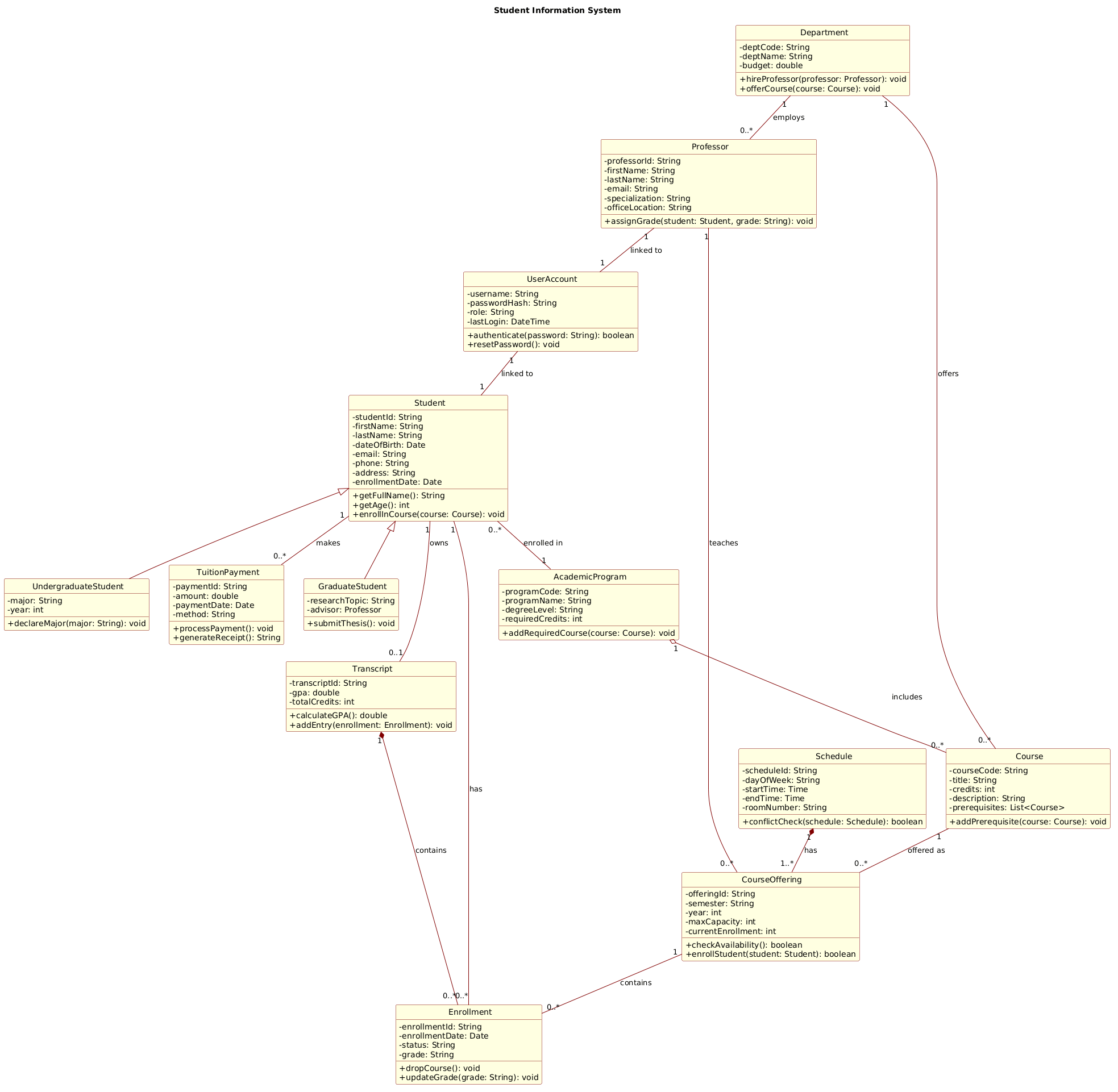
@startuml
!include https://static.visual-paradigm.com/web/resources/plantuml-stdlib/themes/rose.puml

title Student Information System

/'
This class diagram models the core domain entities and their relationships in a typical Student Information System (SIS).
The system manages student enrollment, course offerings, academic records, faculty assignments, and administrative functions.
It captures the hierarchical structure of academic departments and programs, the scheduling of course sections,
the tracking of student grades and transcripts, and the handling of tuition payments.
The diagram also includes user accounts for different roles (students, instructors, and administrators)
and the associated authentication and authorization mechanisms.
'/

class Student {
  -studentId: String
  -firstName: String
  -lastName: String
  -dateOfBirth: Date
  -email: String
  -phone: String
  -address: String
  -enrollmentDate: Date
  +getFullName(): String
  +getAge(): int
  +enrollInCourse(course: Course): void
}

class UndergraduateStudent {
  -major: String
  -year: int
  +declareMajor(major: String): void
}

class GraduateStudent {
  -researchTopic: String
  -advisor: Professor
  +submitThesis(): void
}

class Professor {
  -professorId: String
  -firstName: String
  -lastName: String
  -email: String
  -specialization: String
  -officeLocation: String
  +assignGrade(student: Student, grade: String): void
}

class Course {
  -courseCode: String
  -title: String
  -credits: int
  -description: String
  -prerequisites: List<Course>
  +addPrerequisite(course: Course): void
}

class CourseOffering {
  -offeringId: String
  -semester: String
  -year: int
  -maxCapacity: int
  -currentEnrollment: int
  +checkAvailability(): boolean
  +enrollStudent(student: Student): boolean
}

class Department {
  -deptCode: String
  -deptName: String
  -budget: double
  +hireProfessor(professor: Professor): void
  +offerCourse(course: Course): void
}

class Enrollment {
  -enrollmentId: String
  -enrollmentDate: Date
  -status: String
  -grade: String
  +dropCourse(): void
  +updateGrade(grade: String): void
}

class Transcript {
  -transcriptId: String
  -gpa: double
  -totalCredits: int
  +calculateGPA(): double
  +addEntry(enrollment: Enrollment): void
}

class TuitionPayment {
  -paymentId: String
  -amount: double
  -paymentDate: Date
  -method: String
  +processPayment(): void
  +generateReceipt(): String
}

class Schedule {
  -scheduleId: String
  -dayOfWeek: String
  -startTime: Time
  -endTime: Time
  -roomNumber: String
  +conflictCheck(schedule: Schedule): boolean
}

class AcademicProgram {
  -programCode: String
  -programName: String
  -degreeLevel: String
  -requiredCredits: int
  +addRequiredCourse(course: Course): void
}

class UserAccount {
  -username: String
  -passwordHash: String
  -role: String
  -lastLogin: DateTime
  +authenticate(password: String): boolean
  +resetPassword(): void
}

' Inheritance (Generalization)
Student <|-- UndergraduateStudent
Student <|-- GraduateStudent

' Association
Student "1" -- "0..*" Enrollment : has
Course "1" -- "0..*" CourseOffering : offered as
CourseOffering "1" -- "0..*" Enrollment : contains
Professor "1" -- "0..*" CourseOffering : teaches
Department "1" -- "0..*" Professor : employs
Department "1" -- "0..*" Course : offers

' Aggregation (whole-part, weaker)
AcademicProgram "1" o-- "0..*" Course : includes

' Composition (whole-part, stronger)
Transcript "1" *-- "0..*" Enrollment : contains
Schedule "1" *-- "1..*" CourseOffering : has

' Additional associations
Student "1" -- "0..1" Transcript : owns
Student "1" -- "0..*" TuitionPayment : makes
UserAccount "1" -- "1" Student : linked to
Professor "1" -- "1" UserAccount : linked to

' Association with program
Student "0..*" -- "1" AcademicProgram : enrolled in
@endumlStep-by-Step Architectural Walkthrough
Building a professional diagram requires a structured approach. We will construct this model in four distinct phases, moving from the canvas setup to complex relationship mapping.
Phase 1: Canvas Configuration & Layout Directives
Before defining entities, we must set the stage. We start by including a visual theme to ensure the diagram looks professional immediately. We also define the title and a comment block to provide context for future readers.
First, load the rose.puml theme to apply consistent styling:
!include https://static.visual-paradigm.com/web/resources/plantuml-stdlib/themes/rose.pumlNext, declare the diagram title and add a multi-line comment using /' and '/. This documentation is visible in the rendered output and is crucial for team alignment.
title Student Information System

/'
This class diagram models the core domain entities...
'/
Phase 2: Declaring Core Entities, Actors, and Boundaries
Now we define the classes. In PlantUML, a class is defined using the class keyword followed by the name and a block containing attributes and methods.
Start with the central actor, Student. Notice the visibility modifiers: - for private attributes and + for public methods.
class Student {
  -studentId: String
  -firstName: String
  +getFullName(): String
}
Repeat this pattern for other core entities like Professor, Course, and Department. For specialized roles, we will use inheritance later, but for now, define the base structure.
Phase 3: Mapping Data Flows & Key Interactions
With entities defined, we connect them using relationship lines. The direction and arrowhead style communicate the nature of the relationship.
Association: Use a solid line -- for general connections. For example, a Student has an Enrollment.
Student "1" -- "0..*" Enrollment : hasInheritance: Use a hollow triangle <|-- to show that UndergraduateStudent is a type of Student.
Student <|-- UndergraduateStudentPhase 4: Grouping, Annotations & Visual Polish
Finally, we refine the model with complex ownership relationships. We distinguish between Aggregation (weak ownership) and Composition (strong ownership).
For instance, a Transcript is composed of Enrollment records. If the Transcript is deleted, the specific Enrollment records within that context lose their meaning. This is a composition relationship.
Transcript "1" *-- "0..*" Enrollment : containsReview the diagram in the VPasCode preview pane to ensure all lines are readable and no entities overlap.
Syntax & Keyword Deep Dive
Mastering PlantUML syntax allows you to express complex logic concisely. Here are the key syntax features used in this diagram:
class: Defines a new class entity. The name is followed by a block for members.+and-: Visibility modifiers.+denotes public,-denotes private.<|--: Generalization (Inheritance). The arrow points to the parent class.--: Association. A generic link between two classes.o--: Aggregation. A hollow diamond indicates a "whole-part" relationship where parts can exist independently.*--: Composition. A filled diamond indicates a strong "whole-part" relationship where parts cannot exist without the whole."1"and"0..*": Cardinality notations.1means exactly one,0..*means zero or more.
Best Practices & Pitfalls to Avoid
To maintain a clean and maintainable class diagram, adhere to these modeling best practices:
- Keep Diagrams Modular: If the diagram becomes too crowded, consider splitting it into subsystem views (e.g., one for Academic Management, one for Financials).
- Use Consistent Naming: Always use PascalCase for class names and camelCase for methods to ensure readability.
- Avoid Over-Engineering: Do not model every single database field. Focus on the relationships that drive business logic.
- Validate Cardinalities: Double-check your "1" vs "0..*" notation. A student should not be able to have "1..*" enrollments if the system allows for zero enrollments.
Start Building PlantUML Diagrams Faster with VPasCode
Instantly preview and customize your Student Information System model online in VPasCode without installing any tools.