


In the rapidly evolving landscape of fintech and personal finance management, clarity in system requirements is paramount. Whether you are building a mobile budgeting app or a corporate expense tracking portal, understanding how different actors interact with the system is critical before writing a single line of business logic. Use Case Diagrams serve as the blueprint for these interactions, defining the functional boundaries of your software and ensuring stakeholders agree on what the system does—and what it does not.

Traditionally, creating these diagrams required heavy desktop software or manual drawing tools that often fell out of sync with code documentation. However, with the advent of diagram-as-code tools like VPasCode, software architects can now define system behavior using text-based syntax. This approach integrates seamlessly into development workflows, ensuring your visual documentation evolves alongside your codebase.
In this masterclass, we will construct a comprehensive Use Case Diagram for a Budgeting and Expense Tracker system using PlantUML. We will leverage VPasCode, the free web-based diagram editor, to render the diagram instantly in your browser without installing Java or local dependencies. By the end of this guide, you will understand how to model complex financial workflows, including external integrations like Bank APIs, using clean, maintainable code.
Understanding the Model: Purpose, Scope & Problem Framing
Diagram Abstraction & Representation
A Use Case Diagram is a behavioral model that captures the dynamic aspects of a system. It answers the question: “Who can do what?” In the context of finance, this abstraction is vital for compliance and security auditing. The diagram distinguishes between Actors (external entities like Users, Administrators, or third-party services) and Use Cases (specific functional goals like “Track Expenses” or “Set Budgets”).
Unlike class diagrams which focus on data structure, or sequence diagrams which focus on timing, the Use Case Diagram focuses on intent. It ensures that every feature requested by a stakeholder has a defined entry point and actor association within the system boundary.
Target Domain Scope & Scenario
This tutorial focuses on a Budgeting and Expense Tracker system. The scope includes:
- Core User Functionality: Tracking daily expenses, setting monthly limits, and viewing reports.
- Administrative Oversight: User management and system maintenance for security compliance.
- External Integration: Synchronization with external banking APIs for transaction data.
We intentionally exclude internal database schema details or UI layout specifics to keep the diagram focused on system behavior and actor interactions.
Key Takeaways & Educational Insights
By building this model, you will gain insights into:
- How to define system boundaries using PlantUML rectangles.
- How to represent third-party dependencies (like Bank APIs) as actors.
- How to use the
includerelationship to denote shared functionality between use cases. - How to apply themes (like
cerulean) for professional visual consistency.
Complete Diagram & Full Source Code
Below is the finished blueprint for the Budgeting and Expense Tracker system. You can visualize the end goal immediately, then examine the code to understand the construction logic.
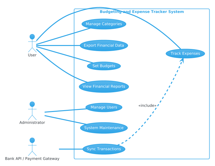
Copy the following complete source code to see the diagram render in VPasCode:
@startuml
!theme cerulean
left to right direction
skinparam packageStyle rectangle

actor User as "User"
actor Admin as "Administrator"
actor Bank as "Bank API / Payment Gateway"

rectangle "Budgeting and Expense Tracker System" {
  usecase "Track Expenses" as UC1
  usecase "Set Budgets" as UC2
  usecase "View Financial Reports" as UC3
  usecase "Manage Categories" as UC4
  usecase "Export Financial Data" as UC5
  usecase "Sync Transactions" as UC6
  usecase "Manage Users" as UC7
  usecase "System Maintenance" as UC8
}

User -- UC1
User -- UC2
User -- UC3
User -- UC4
User -- UC5

Bank -- UC6

Admin -- UC7
Admin -- UC8

UC6 ..> UC1 : <<include>>
@endumlStep-by-Step Architectural Walkthrough
Now that you have the full picture, let’s deconstruct the diagram into four logical phases. This method ensures you build diagrams that are scalable and easy to maintain.
Phase 1: Canvas Configuration & Layout Directives
Before defining actors, we must set the stage. VPasCode supports various themes and layout directions. For financial diagrams, a clean, professional look is preferred.
We begin by setting the theme to cerulean, which provides a soft blue color palette suitable for enterprise software. We also enforce a left to right direction to align with standard reading patterns.
!theme cerulean
left to right direction
skinparam packageStyle rectangle
The skinparam packageStyle rectangle directive ensures that system boundaries are drawn as solid rectangles rather than rounded boxes, which is standard for Use Case diagrams.
Phase 2: Declaring Core Entities, Actors, and Boundaries
Actors represent roles outside the system but interacting with it. In finance, trust and external validation are key, so we define the User, Administrator, and Bank explicitly.
actor User as "User"
actor Admin as "Administrator"
actor Bank as "Bank API / Payment Gateway"
Next, we define the system boundary using the rectangle keyword. Everything inside this box is part of the Budgeting and Expense Tracker System.
rectangle "Budgeting and Expense Tracker System" {
  // Use cases go here
}
Phase 3: Mapping Data Flows & Key Interactions
Inside the boundary, we declare the use cases. Each use case represents a specific goal. We use the usecase keyword and assign a unique ID (like UC1) for easier referencing later.
usecase "Track Expenses" as UC1
usecase "Set Budgets" as UC2
Once defined, we connect actors to use cases using solid lines (--). This indicates a direct association. For example, the User is associated with tracking expenses and setting budgets.
User -- UC1
User -- UC2
Crucially, we also model external dependencies. The Bank actor connects to the Sync Transactions use case, indicating that external data flows into the system via this function.
Phase 4: Grouping, Annotations & Visual Polish
Finally, we refine the relationships. Not all interactions are direct associations. Some use cases rely on others. We use the ..> (dashed arrow) with the <<include>> stereotype to show that Sync Transactions must include the functionality of Track Expenses.
UC6 ..> UC1 : <<include>>This annotation clarifies that you cannot sync transactions without recording them as expenses first, enforcing a logical dependency in your architecture.
Syntax & Keyword Deep Dive
To master PlantUML within VPasCode, you need to understand the specific keywords used in this diagram. Here is a breakdown of the essential syntax:
@startuml/@enduml: These delimiters mark the beginning and end of the diagram definition. Everything between them is processed by the rendering engine.!theme cerulean: A preprocessor directive that loads theceruleanvisual theme, controlling colors and fonts globally.actor: Defines an external entity. The syntaxactor Name as "Label"allows you to assign a shorter internal ID while displaying a friendly name.rectangle: Creates a system boundary. Use cases inside this block are considered internal to the system.usecase: Defines a functional unit. Using an alias (e.g.,as UC1) helps keep connection lines clean.--: Represents a direct association (solid line) between an actor and a use case...>: Represents a dependency or include relationship (dashed arrow).<<include>>: A stereotype indicating that one use case incorporates the behavior of another.
Best Practices & Pitfalls to Avoid
When modeling financial systems, clarity is non-negotiable. Follow these best practices to ensure your diagrams remain effective documentation:
- Keep Actors Distinct: Avoid creating too many actors. If two actors perform the same tasks, consider merging them into a generalized role unless their permissions differ significantly (e.g., User vs. Admin).
- Use Meaningful Labels: Use case names should start with a verb (e.g., “Track Expenses” not “Expense Tracking”) to clearly denote action.
- Limit Scope: Do not mix architectural details (like database tables) with behavioral details (use cases). Keep your Use Case Diagram focused on functionality.
- Validate Dependencies: Ensure that
includerelationships make logical sense. If a feature can exist independently, do not force an include relationship.
Try It Yourself with VPasCode
Start Building PlantUML Diagrams Faster with VPasCode
Instantly prototype your Budgeting and Expense Tracker architecture online in VPasCode without installing any tools.