


In the realm of government software architecture, clarity is not just a design preference—it is a compliance requirement. When developing systems like a Tax Processing Engine, stakeholders must have an unambiguous view of how different user roles interact with the core functionality. A Use Case Diagram provides this high-level abstraction, mapping out the goals (use cases) that external actors (users or systems) aim to achieve within a defined system boundary.
For architects and developers, maintaining this documentation in a static format often leads to drift between the code and the design. Using PlantUML within VPasCode transforms this process into a living documentation workflow. By treating diagrams as code, you ensure that the visual representation of your tax processing logic remains synchronized with the system’s actual behavior, allowing for rapid prototyping and instant validation without the need for local environment setup.
Understanding the Model: Purpose, Scope & Problem Framing
Diagram Abstraction & Representation
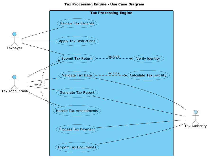
A Use Case Diagram models the functional requirements of a system from the perspective of its users. In this specific Tax Processing Engine model, we are not detailing internal algorithms or database schemas. Instead, we are defining the what and who of the system. Actors represent the roles (e.g., Taxpayer, Tax Accountant) that initiate actions, while Use Cases represent the specific functional goals (e.g., Submit Tax Return, Validate Tax Data) the system must fulfill.
Target Domain Scope & Scenario
This diagram focuses specifically on the Tax Processing Engine system boundary. It intentionally excludes upstream data ingestion pipelines or downstream payment gateway integrations, focusing instead on the core interaction layer. The scope includes the primary users submitting data, secondary systems verifying compliance (Tax Authority), and the internal logic required to calculate liabilities and handle amendments.
Key Takeaways & Educational Insights
By constructing this model, you will gain clarity on system boundaries, ensuring that external dependencies (like the Tax Authority) are clearly distinguished from internal processes. You will also learn how to properly structure associations to reflect real-world workflows, distinguishing between direct user actions and system-to-system interactions.
Complete Diagram & Full Source Code
Below is the complete blueprint for the Tax Processing Engine Use Case Diagram. This visualization defines the primary actors on the left, secondary actors on the right, and the core functionality encapsulated within the system boundary.
@startuml
!include https://static.visual-paradigm.com/web/resources/plantuml-stdlib/themes/vp.puml

title Tax Processing Engine - Use Case Diagram

/'
This diagram illustrates the core functionality of a Tax Processing Engine system,
which handles tax calculation, validation, and reporting for various business scenarios.
The system serves taxpayers who need to submit their tax information and receive
accurate calculations, while also interfacing with government tax authorities for
compliance and reporting purposes. The engine supports multiple tax types, handles
complex deduction scenarios, and ensures regulatory compliance through automated
validation and error checking processes.
'/

left to right direction

actor "Taxpayer" as taxpayer
actor "Tax Accountant" as accountant
actor "Tax Authority" as authority #LightBlue

rectangle "Tax Processing Engine" {
    usecase "Submit Tax Return" as submitReturn
    usecase "Calculate Tax Liability" as calculateTax
    usecase "Validate Tax Data" as validateData
    usecase "Generate Tax Report" as generateReport
    usecase "Process Tax Payment" as processPayment
    usecase "Review Tax Records" as reviewRecords
    usecase "Apply Tax Deductions" as applyDeductions
    usecase "Handle Tax Amendments" as handleAmendments
    usecase "Verify Identity" as verifyIdentity
    usecase "Export Tax Documents" as exportDocs
}

' Primary actors on the left
taxpayer -- submitReturn
taxpayer -- applyDeductions
taxpayer -- reviewRecords

accountant -- submitReturn
accountant -- validateData
accountant -- generateReport
accountant -- handleAmendments

' Secondary actors on the right
validateData --- authority
generateReport --- authority
processPayment --- authority
exportDocs --- authority

' Include relationships
submitReturn ..> verifyIdentity : include
validateData ..> calculateTax : include

' Extend relationship
handleAmendments .> submitReturn : extend

@endumlStep-by-Step Architectural Walkthrough
Phase 1: Canvas Configuration & Layout Directives
Every professional diagram begins with a consistent theme and layout. We start by including the Visual Paradigm standard theme to ensure the diagram matches enterprise branding standards. We also set the layout direction to left to right, which is a common convention for Use Case Diagrams to allow actors to flow naturally into the system boundary.
!include https://static.visual-paradigm.com/web/resources/plantuml-stdlib/themes/vp.puml

left to right direction
Phase 2: Declaring Core Entities, Actors, and Boundaries
Next, we define the external participants and the system itself. Actors are declared using the actor keyword, and we assign aliases (e.g., as taxpayer) to reference them later in relationships. The system boundary is created using the rectangle keyword, which encapsulates all internal use cases.
actor "Taxpayer" as taxpayer
actor "Tax Accountant" as accountant
actor "Tax Authority" as authority #LightBlue

rectangle "Tax Processing Engine" {
    usecase "Submit Tax Return" as submitReturn
    ... (other use cases)
}
Phase 3: Mapping Data Flows & Key Interactions
With the canvas ready, we map the interactions. Primary actors are placed on the left and connect to use cases using simple associations (no arrowheads). Secondary actors, representing external dependencies like the Tax Authority, connect to specific use cases that require external validation or reporting. We also define logical dependencies using include and extend relationships to show mandatory or optional behaviors.
taxpayer -- submitReturn
validateData --- authority
submitReturn ..> verifyIdentity : include
Phase 4: Grouping, Annotations & Visual Polish
Finally, we add context to the diagram. A title is added at the top, and a comment block is included to describe the diagram’s purpose. This documentation lives directly in the code, ensuring that anyone reviewing the file understands the context without needing external documentation.
title Tax Processing Engine - Use Case Diagram

/'
This diagram illustrates the core functionality...
'/
Syntax & Keyword Deep Dive
To build robust diagrams in PlantUML, understanding the specific syntax for relationships and actors is crucial. Here is a breakdown of the key keywords used in this Tax Processing Engine model:
actor: Defines an external entity interacting with the system. Aliases (e.g.,as taxpayer) allow for cleaner relationship definitions later.usecase: Represents a specific function or goal within the system boundary. Each use case should have a unique alias.rectangle: Creates the system boundary box that groups all internal use cases together.--: Creates a solid line association without arrowheads, typically used for primary actor interactions...>: Represents anincluderelationship, indicating that one use case must always invoke another (e.g., Submitting a return includes verifying identity)..>: Represents anextendrelationship, indicating optional behavior that extends a base use case under certain conditions (e.g., Amendments extend a standard submission)./' ... '/: Defines a comment block that is rendered as text within the diagram but does not affect the logic.
Best Practices & Pitfalls to Avoid
- Define Clear System Boundaries: Always enclose use cases in a rectangle. This clearly distinguishes between what the system does and what external actors do.
- Consistent Naming Conventions: Use verb-noun phrases for use cases (e.g., "Submit Tax Return") to maintain readability and consistency.
- Minimize Complexity: If a diagram becomes too crowded, consider splitting it into subsystems. For example, separate the "Payment Processing" logic into its own diagram if it grows too complex.
- Use Comments for Context: Don’t rely solely on the visual. Use the
/' ... '/comment block to document the business rules or scope of the diagram.
Start Building Use Case Diagrams Faster with VPasCode
Instantly render and customize your Tax Processing Engine diagram online in VPasCode without installing any tools.